
Home - Search - Browse - Alphabetic Index: 0- 1- 2- 3- 4- 5- 6- 7- 8- 9
A- B- C- D- E- F- G- H- I- J- K- L- M- N- O- P- Q- R- S- T- U- V- W- X- Y- Z
Apollo M-1
 Apollo M1 Credit: NASA |
Status: Study 1962. Height: 14.10 m (46.20 ft).
Command, mission, and propulsion modules were designed primarily for lunar orbit, with flexibility and growth potential built in for more advanced missions (such as a lunar landing) with the same basic vehicle design. The preferred command module was a flat-topped blunt half cone lifting-body concept, similar to the HL-10 shape developed by Alfred Eggers at Ames.
The re-entry vehicle was 3.17 m long, 3.66 m across, had a total mass of 2,540 kg, and a hypersonic L/D ratio of 0.52. Earth landings would be by glidesail parachute near San Antonio, Texas. The command module, with an abort tower attached through launch, would nestle inside a large pressurized mission module (a similar approach would be used in Russia for the L3M lunar landing spacecraft of 1972-1974). The circumlunar version would have a total length of 14.1 m.
What Astronautics proposed was similar in its mode of operation to the command and service modules that ultimately evolved for Apollo. Convair/Astronautics envisioned mission planning as building progressively upon many earth-orbital flights before attempting circumlunar and then lunar-orbital missions. Elementary experiments that would evolve into rendezvous, docking, artificial gravity, maneuverable landing, and an eventual lunar landing were foreseen. A total Apollo cost of $1.25 billion over about six years was estimated. The study cost the contractor about $1 million, four times what NASA paid the company.
The M-1 re-entry vehicle coupled with the modular concept configuration provided limitless versatility for manned space systems. Growth versions seemed possible in many areas. The heat shielding, control, and landing systems offered the greatest areas of design evolution. The propulsion system selected was not likely to be superseded throughout the Apollo program.
Alternate ablative materials and ceramics under development could be progressively applied to the Apollo vehicle as heat shielding technology advanced. The parachute landing system could be superseded by the paraglider to permit glide control and reduced impact. Stability and control testing of the M-1 shape would yield applicable data for reducing flap size, weight, and cross coupling effects. The elimination of control flaps was the goal of feasibility studies currently underway on the reentry roll maneuver.
The Apollo vehicle offered a logical development system for cooperative manned space vehicle rendezvous techniques. The interchangeable modular design provided distinct assembly advantages for special subsysterns related to the rendezvous technique. One such subsystem, the retractable airlock, was given special study.
The manned lunar landing vehicle could also emerge from the Apollo program. The propulsion module with jettisonable tanks then became the dominant module.
A highly tapered M-1 type vehicle possessing the same re-entry stability and heating characteristics and which also achieved an L/D adequate for glide landings was under test. The experience to be gained with the M-1 shape could build a technical foundation for successively larger and cleaner re-entry shapes such as the M-2.
Eventually, the requirement to re-enter, fly in, and land at an existing airport, or to ferry vehicles from one base to another would be justifiable. As re-entry vehicles grow in size and complexity, the ferry version would inevitably appear. The M-3 vehicle with foldable wings was one logical evolution from the M-2. Ferry flights would be powered and fuelled by detachable engines and fuel pods. Thus, the M series vehicles, as created by NASA research, provided a versatile spectrum of space re-entry vehicles. Each advancement would not require a complete new concept, and experience obtained by development of its predecessors can be used.
Although the re-entry vehicle was sized for three men, it was roomy with adequate consideration for confinement psychology. Alternate interior arrangements were possible to include two additional men if needed for a rescue mission.
The volume requirements of space station living, crew exchange, highly instrumented, or specially equipped missions were all adequately provided for with the mission module concept presented. The modular design permitted a volume to weight ratio that was significantly higher than other integrated vehicle designs.
The simple concept of a single ablator heat shield was used in the selected design and was considered the most reliable use of presently available materials. The Avcoat X-5000 series ablation materials represented an attempt to obtain the char stability of the best high temperature ablators while at the same time obtaining insulation effectiveness in a single material. These goals were not entirely compatible, and the resulting material represented a compromise solution to the problem.
Convair felt that an extendible airlock was the best solution for docking and spacewalks - both in orbit and on the lunar surface. The design was interesting because of its similarity to those used by the Soviets in the Voskhod spacecraft and possibly for the L1 Podsadka variant circumlunar mission. In Convair's scheme, before vehicles began the rendezvous sequence, each extended and pressurized its airlock. As the probe and receptacle cables reeled the vehicles closer together, attitude control jets were used to maintain cable tension and align vehicles for mating airlocks. Jets were vectored toward the mating vehicle to keep a slight separation force between vehicles and eliminate collision danger.
Additional misalignment compensation was provided by control of the angle of the airlock mating flanges (the astronaut had an omnidirectional control handle). Both pilots monitored positions of vehicles with bore-sighted TV, throughout the rendezvous procedure.
As airlocks make contacted and latched together, low internal pressure allowed airlocks to act as shock absorbers. When pressure seals in the mating rings were inflated, "safe" indication was registered on the vehicle instrument panel. If "unsafe" indication was noted, pressure suited astronauts crewman inside the vehicle, would open the inner hatch and aid the injured man back into the vehicle.
The mechanical advantages of the airlock were:
- The minimum volume package had low drag during boost.
- It required no compromise of internal arrangement of either vehicle.
- By being mounted on the mission module, it eliminated added weight and structural modifications to the re-entry vehicle.
- External position precluded design for compressive pressure loads, thereby permitting use of a plastic-lined metal-weave bellows.
- The estimated weight was 120 pounds.
- Rendezvous could be performed, if only one vehicle were equipped with an airlock, providing the other vehicle had an external flange to receive airlock latches.
- The airlock package could be used on any vehicle by mounting over the external hatch. It could be used, regardless of shape of the vehicle hatch so long as the maximum dimension fits within the airlock
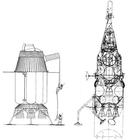
The Apollo vehicle recommended was readily adaptable to lunar landing missions. The primary change was replacement of the circumlunar propulsion module with a larger, dual-purpose system. The module concept was well suited to orbital assembly. Four configurations of differing propellant tank and engine arrangements were considered. The design selected involved a multiple tank system with the lunar landing units jettisoned prior to takeoff.
For lunar takeoff, propulsion was furnished by one 37.5K engine mounted on the central cylindrical tank. For landing, the center engine was used together with two other 37.5K engines, utilizing all tanks except the center one. Attitude control was provided by the existing engines mounted on the mission module during takeoff and by the two 4K engines during landing.
The clustered, pressure-stabilized, cylindrical tanks provided an ideal combination of light weight, reliability, and ease of manufacture. Dimensions of the cylinders and oblate spheroid bulkheads, were such that, for the tank pressures used, near minimum gage titanium alloy was adequate. For additional reliability, tanks were stiffened sufficiently so that loss of pressure would not cause vehicle damage under static ground loads. Considerable adapter weight was saved by utilizing the H2 landing tank to transmit vehicle loads to the booster stage below. Overall length was minimized by the internal conical tie-in structure inside the tank. These cones distribute the concentrated loads on the tank ends over the full pressurized areas, and were used both as main engine thrust structure, and to connect the lunar vehicle to the lower stage. Inter-tank shear structure was also shown.
Liquid oxygen used during landing was stored in two small tanks, to maintain weight symmetry. The spaces at 90 degree angles to the O2 tanks, between the H2 tanks, were used for storage of solar cells, antennae, etc. The latter were attached to the mission module, and were available on the return trip to earth, after the landing tanks have been jettisoned.
The lunar launch tank was supported by the mission module. Conically arranged struts connected this tank to the forward adapter. Attachment of the forward adapter was the only structural change required in either of the manned modules for Apollo adaptation to the lunar landing mission.
The aerodynamic fairing surrounding the tanks for earth launch provided an excellent meteorite shield. Note that the vital lunar takeoff tank, by its central position, was well protected with this arrangement.
The landing gear served as a shock absorber, leveler for sloping ground, and lunar launch platform. Unmanned lunar exploration would undoubtedly furnish information about the moon's surface which would be used to optimize landing gear design.
One other necessary addition to the Apollo vehicle for lunar landing was the airlock. The airlock could be jettisoned to lighten the return take-off load.
The lunar landing assumed an approach to landing from a low altitude, nominally circular orbit. Another possible approach technique was the direct approach to the moon's surface without any intermediate parking orbit. Although this latter method was somewhat more efficient, the use of a parking orbit allowed greater flexibility in the choice of a landing site and allows more time for evaluation of the sites. Furthermore, the progressive approach to landing by the use of a parking orbit permitted a complete evaluation of the state of the mission at several stages with the possibility of returning to the earth prior to the actual descent to the surface of the moon.
The choice of a lunar orbit would be made prior to launch and this choice would be reflected in the detailed constants of the launch guidance equations. Similarly, midcourse guidance would correct for deviations in the earth-moon trajectory so that the spacecraft would arrive at the required location with the required velocity for entry into the lunar orbit. In all significant aspects, the problems of launch and midcourse guidance were identical to those for a close pass orbit and the expected accuracies would also be identical.
After entering the lunar orbit, prior to the descent to the surface, the orbit would be accurately established by observations with an altimeter and horizon scanner. These techniques would be supplemented by occultation observations and verified by visual observations of the surface of the moon. During the moon orbiting phase site selection would be verified.
With an orbit accurately established, the descent to the surface of the moon was accomplished in three steps. The first step was a transfer ellipse to bring the spacecraft within a few miles (five or less) from the lunar surface. This ellipse was entered by applying a small decrement of velocity somewhere between a quarter revolution and a half revolution from the landing area. Normally this decrement would include a small plane change to place the spacecraft at a site selected near, but not exactly on, the ground track of the lunar orbit. The exact point at which the velocity decrement was applied would be determined by the amount of plane change incorporated into the maneuver. Specifically for no plane change a Hohmann transfer would be used. For a relatively large plane change the velocity decrement would be applied closer to 90 degrees from the landing site.
The second step removed most of the velocity, which was largely horizontal, such that the vehicle descends almost vertically to the surface. For this phase and for the remainder of the landing maneuver an additional set of sensing equipment would be employed. This equipment consisted of a low altitude altimeter and a multiple-beam Doppler radar for measuring horizontal and vertical velocity with respect to the surface.
The third step was the final approach and the touchdown maneuver for a soft landing. During the final approach, the landing area was surveyed for possible obstacles, and any necessary maneuvering to avoid these was performed. Finally, all horizontal and vertical velocity was removed as the altitude approached zero so that touchdown velocities of a few feet per second were achieved.
The problem of departure from the lunar surface involved nearly the same problems as departure from a lunar orbit. It was necessary to establish a reference orbit (as a function of time) which originated near the lunar landing site and terminated at a point near the earth such that re-entry and landing at a preselected site on the earth can take place.
The modular design of the Apollo vehicle made it unnecessary to redesign it for the lunar landing mission. Only the lunar landing and launch propulsion modules need be added to the vehicle. While design of these modules was in process the basic Apollo vehicle would be proving itself in earth orbital and circumlunar flights. Larger boosters and, possibly, orbital refueling techniques would also be under development in the interim. The configuration selected, provided the lightest practical lunar launch stage. Elimination of long inter-stage adapters; duplicate application of the lunar launch engine for landing, reliability inherent with multiple tanks, protection afforded the internally mounted take-oft tank, and ease of manufacture all contributed to establishing this preference.
Performance Requirements for a Soft Lunar Landing and Return
- Midcourse Corrections (Outgoing). 250 ft/sec
- Enter 60-n. mi. Orbit (From 3.5-Day Trajectory). 2920 ft/sec
- Transfer to 3-n. mi. Periselenium Orbit. 250 ft/sec - Includes small plane change
- Remove Horizontal Velocity at 3-n. mi. Altitude. 5370 ft/sec
- Final Descent From 1-n. mi. Altitude. 670 ft/sec - Includes 100 ft/sec losses (gravity) + 150 ft/sec losses (maneuverable)
- Ascent to Return Ellipse (Direct). 8850 ft/sec - Includes 350 ft/sec losses (gravity) + 100 ft/sec losses (maneuvering)
- Midcourse Corrections (Incoming) 350 ft/sec
- TOTAL 18,660 ft/sec
Lunar Landing - Apollo Weight Comparisons
- Lunar Launch Stage (1723) lbs
- Structure (includes tanks and insulation) 583 lbs
- Propulsion 550 lbs
- Pneumatics 190 lbs
- Hydraulics 41 lbs
- Electrical 10 lbs
- Propellant Utilization 35 lbs
- Residuals 314 lbs
- Lunar Landing Stage (5026) lbs
- Structure 1913 lbs
- Propulsion 1470 lbs
- Pneumatics 380 lbs
- Hydraulics 83 lbs
- Electrical 25 lbs
- Propellant Utilization 89 lbs
- Residuals 1066 lbs
Weight Analysis - Configuration I - Based on 10,406 Pound Payload; 1,653 Pound Lunar Launch Step; 5,026 Pound Lunar Landing Step
- Entry Vehicle: 5,700 lbs
- Mission Module Jettison 3,606 lbs
- Stage Burnout 9,306 lbs
- Moon-Earth Midcourse Correction 340 lbs
- Return Vehicle Initial 9,646 lbs
- Lunar Launch Jettison 1,723 lbs
- Lunar Launch Burnout 11,369 lbs
- Lunar Launch Propellants 10,714 lbs
- Lunar Launch Initial 22,083 lbs
- Propellant Boiled-off 700 lbs
- Landing Weight of Lunar Launch Stage 22,783 lbs
- Jettison on Moon 5,026 lbs
- Lunar Landing Vehicle Burnout 27,809 lbs
- Lunar Landing Vehicle Initial 53,791 lbs
- Propellant Boiled-off 2,500 lbs
- Earth-Moon Vehicle Burnout 56,291 lbs
- Earth-Moon Midcourse Correction 2,234 lbs
- Earth-Moon Vehicle Initial 58,525 lbs
It was most efficient to use liquid hydrogen as fuel for both the launch and landing stages because:
a. The propellant loss caused by boil off was small.
b. The powered flight time was relatively long which eases terminal guidance problems.
The optimum initial thrust-to-weight (earth pounds) ratio for lunar landing was in the range of 0.5 to 0.6. The powered descent time was the order of six minutes. The starting altitude was sufficiently high to permit a circumlunar abort trajectory in case of landing propulsion failure. The reduction in gravity losses by increasing thrust was offset by the higher weight of the propulsion system. Lowering the thrust-to-weight ratio below 0.5 would increase gravity losses.
It appeared that constant thrust descent rockets had advantages over variable thrust engines (higher specific impulses, increased reliability, simpler design, etc. ). One or two high thrust engines with restart capability provided the main retrothrust for the descent phase. Thrust control for landing was obtained by swiveling two or more smaller engines. Their combined thrust was approximately one-sixth of the total thrust of the landing stage. They would also be used for midcourse orbit corrections on the earth to moon trip. The proposed method of terminal thrust control would minimize whirling up dust from the moon's surface.
Family: Manned spacecraft. Country: USA. Launch Vehicles: Saturn V. Agency: Convair. Bibliography: 2301.
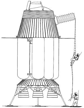 | Apollo M-1 Lunar lander version of Apollo M-1 (on lunar surface) |
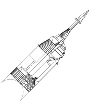
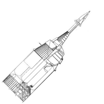 | Apollo M-1 Lunar lander version of Apollo M-1 (launch configuration) |
 | Apollo M-1 |
 | Apollo M-1 Apollo M-1 airlock configurations. |
 | Apollo Landers 1961 Martin and Convair designs for Apollo lunar landers, May-June 1961 |
Back to top of page
Home - Search - Browse - Alphabetic Index: 0- 1- 2- 3- 4- 5- 6- 7- 8- 9
A- B- C- D- E- F- G- H- I- J- K- L- M- N- O- P- Q- R- S- T- U- V- W- X- Y- Z
© 1997-2019 Mark Wade - Contact
© / Conditions for Use