Home - Search - Browse - Alphabetic Index: 0- 1- 2- 3- 4- 5- 6- 7- 8- 9
A- B- C- D- E- F- G- H- I- J- K- L- M- N- O- P- Q- R- S- T- U- V- W- X- Y- Z
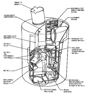
MOL LM

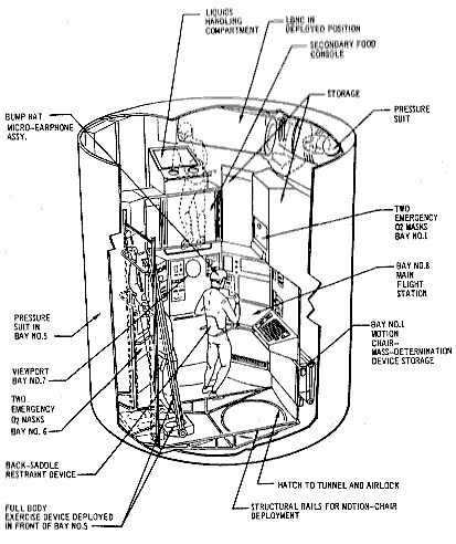
MOL LM View 2
MOL Lab Module cutaway
Credit: McDonnell Douglas
AKA: Laboratory Module. Status: Cancelled 1969. Payload: 2,700 kg (5,900 lb). Specific impulse: 255 s. Height: 5.80 m (19.00 ft). Diameter: 3.05 m (10.00 ft).
The 0.81 m diameter crew transfer tunnel ran through the forward section from the hatch in the heat shield of the Gemini through the center of the section. Around the tunnel were arranged cryogenic storage tanks of helium, hydrogen, and oxygen for the crew atmosphere and fuel cells. Also located in this section were the environmental control system, fuel cells for electrical power, four ATCS quad attitude control thruster assemblies and their propellant tanks.
The aft portion of the Laboratory Module was arranged into two 'stories', with vertical being the same orientation as on the pad. The upper bulkhead had a hatch leading to the crew transfer tunnel. Each story was furnished in eight bays, in a structure dubbed 'the birdcage'.
Arranged around the 'upper story', going clockwise, Bay 1 - large storage compartments; Bay 2 - environmental control system equipment; Bay 3 - hygiene/waste compartment; Bay 4 - a biochemical test console and work station; Bay 5 and 6 - a large experiment airlock; Bay 7 - a glove box for liquids handling; below that a secondary food console; and Bay 8 - additional storage compartments. Mounted horizontally near the ceiling, over Bay 7, 8, and 1 was a bed for one crew member and spacesuit stowage. There was no 'floor' between the first and second stories -- crew members were free to float between them during operations.
The 'lower floor' began with Bay 1 - a motion chair that slid out on rails to determine mass of the crew members during the flight; Bay 2 - two performance test panels; Bay 3 - the environmental control system controls; Bay 4 - a physiology test console; Bay 5 - a full-body exercise device; Bay 6 - two emergency oxygen masks; Bay 7 - viewport and instrument panel; and Bay 8 - the main spacecraft control station.
In the lower bulkhead a second hatch that led to a tunnel to an aft-mounted docking collar or an airlock in the mission module - the exact use would depend on the mission payload. The pressurized Laboratory Module was the load-carrying structure, but it was surrounded by an outer shroud. This was set out from the inner pressure vessel by titanium stand-offs and there were 20 layers of Mylar insulation between the outer shroud and the inner pressure vessel. The shroud protected the MOL during ascent through the atmosphere, and served as an insulator, meteorite shield, and provided some radiation protection.
Crew Size: 2. Habitable Volume: 11.30 m3. RCS Coarse No x Thrust: ? x 107 N. RCS specific impulse: 289 sec. Spacecraft delta v: 101 m/s (331 ft/sec). Electric System: 2,000.00 kWh. Electric System: 2.00 average kW.
Family: Space station module. Country: USA. Spacecraft: MOL. Propellants: Solid.
 | MOL LM View 1 MOL Lab Module cutaway Credit: McDonnell Douglas |
Back to top of page
Home - Search - Browse - Alphabetic Index: 0- 1- 2- 3- 4- 5- 6- 7- 8- 9
A- B- C- D- E- F- G- H- I- J- K- L- M- N- O- P- Q- R- S- T- U- V- W- X- Y- Z
© 1997-2019 Mark Wade - Contact
© / Conditions for Use