
Home - Search - Browse - Alphabetic Index: 0- 1- 2- 3- 4- 5- 6- 7- 8- 9
A- B- C- D- E- F- G- H- I- J- K- L- M- N- O- P- Q- R- S- T- U- V- W- X- Y- Z
Apollo LRV
LRV Drawing
Credit: NASA
AKA: Lunar Roving Vehicle. Status: Operational 1971. Gross mass: 208 kg (458 lb).
The collapsible 208 kg battery-powered rover could take two astronauts, 55 kg of scientific equipment, and 27 kg of lunar samples over a cumulative distance of 92 kilometers during one lunar day.
Weighing about 208 kilograms (457 pounds), Earth weight when deployed on the Moon, the LRV could carry a total payload of about 490 kilograms (1,080 pounds), more than twice its own weight. The payload included two astronauts and their portable life support systems (about 353 kilograms; 800 pounds), 45.4 kilograms (100 pounds) of communications equipment, 54.5 kilograms (120 pounds) of scientific equipment and photographic gear, and 27.2 kilograms (60 pounds) of lunar samples.
The LRV was designed to operate for a minimum of 78 hours during :the lunar day. It could make several exploration sorties to a cumulative distance of 92 kilometers (57 miles). The maximum distance the LRV was permitted to range from the lunar module was approximately 9.7 kilometers (six miles), the distance the crew could safely walk to the LM in the unlikely event of a total LRV failure. This walk-back distance limitation was based upon the quantity of oxygen and coolant available in the astronauts' portable life support systems. This area contained about 290 square kilometers (113 square miles) available for investigation, 10 times the area that could be explored on foot.
The vehicle could negotiate obstacles 30.5 centimeters (one foot) high, and cross crevasses 70 centimeters wide (28 inches). The fully loaded vehicle could climb and descend slopes as steep as 25 degrees, and park on slopes up to 35 degrees. Pitch and roll stability angles were at least +-45 degrees, and the turn radius was three meters (10 feet).
Both crewmen sat so the front wheels were visible during normal driving. The driver used an on-board dead reckoning navigation system to determine direction and distance from the lunar module, and total distance traveled at any point during a traverse.
The LRV consisted of five major systems: mobility, crew station, navigation, power, and thermal control. Secondary systems included the deployment mechanism, LM attachment equipment and ground support equipment.
The aluminum chassis was divided into three sections that supported all equipment and systems. The forward and aft sections fold over the center one for stowage in the LM. The forward section held both batteries, part of the navigation system, and electronics gear for the traction drive and steering systems. The center section held the crew station with its two seats, control and display console; and hand controller. The floor of beaded aluminum panels could support the weight of both astronauts standing in lunar gravity. The aft section held the scientific payload.
Auxiliary LRV equipment included the lunar communications relay unit (LCRU) and its high and low gain antennas for direct communications with Earth, the ground commanded television assembly (GCTA), a motion picture camera, scientific equipment, tools, and sample stowage bags.
Mobility System
The mobility system was the major LRV system, containing the wheels, traction drive, suspension, steering, and drive control electronics subsystems.
The vehicle was driven by a T-shaped hand controller located on the control and display console post between the crewmen. Using the controller, the astronaut maneuvered the LRV forward, reverse, left and right.
Each LRV wheel had a spun aluminum hub and a titanium bump stop (inner frame) inside the tire (outer frame). The tire was made of a woven mesh of zinc-coated piano wire to which titanium treads were riveted in a chevron pattern around the outer circumference. The bump stop prevented excessive inflection of the mesh tire during heavy impact. Each wheel weighed 5.4 kilograms (12 pounds) on Earth and was designed to be driven at least 180 kilometers (112 miles). The wheels were 81.3 centimeters (32 inches) in diameter and 22.9 centimeters (nine inches) wide.
A traction drive attached to each wheel had a motor harmonic drive gear unit, and a brake assembly. The harmonic drive reduced motor speed at an 80-to-1 rate for continuous operation at all speeds without gear shifting. The drive had an odometer pickup (measuring distance traveled) that sent data to the navigation system. Each motor developed 0.18 kilowatt (1/4-horsepower) and operated from a 36-volt input.
Each wheel had a mechanical brake connected to the hand controller. Moving the controller rearward de-energized the drive motors and forced brake shoes against a drum, stopping wheel hub rotation. Full rear movement of the controller engaged and locked a parking brake.
The chassis was suspended from each wheel by two parallel arms mounted on torsion bars and connected to each traction drive. Tire deflection allowed a 35.6-centimeter (11-inch) ground clearance when the vehicle was fully loaded and 43.2 centimeters (17 inches) when unloaded.
Both front and rear wheels had independent steering systems that allowed a "wall-to-wall" turning radius of 3.1 meters (122 inches), exactly the vehicle length. If either set of wheels had a steering failure, its steering system could be disengaged and the traverse could continue with the active steering assembly. Each wheel could also be manually uncoupled from the traction drive and brake to allow "free wheeling" about the drive housing.
Pushing the hand controller forward increased forward speed; rear movement reduced speed. Forward and reverse were controlled by a knob on the controller's vertical stem. With the knob pushed down, the controller could only be pivoted forward; with it pushed up, the controller could be pivoted to the rear for reverse.
Crew Station
The crew station consisted of the control and display console, seats, seat belts, and armrest, footrests, inboard and outboard handholds, toeholds, floor panels, and fenders.
The control and display console was separated into two main parts: The top portion held navigation system displays; the lower portion contained monitors and controls. Attached to the upper left side of the console was an attitude indicator that showed vehicle pitch and roll.
At the console top left was a position indicator. Its outer circumference was a large dial that showed vehicle heading (direction) with respect to lunar north. Inside the dial were three digital indicators that showed bearing and range to the LM and distance traveled by the LRV. In the middle of the console upper half was a Sun compass device that was used to update the LRV's navigation system. Down the left side of the console lower half were control switches for power distribution, drive and steering, and monitors for power and temperature. A warning flag atop the console was set whenever a temperature went above limits in either battery drive motor.
| Bendix LSSM American manned lunar rover. Study 1965. The Bendix LSSM lunar rover design of October 1965 had 4 wheels. and a range of 400 km with a crew of 2 on a 14 day traverse. |
| Boeing LSSM American manned lunar rover. Study 1965. The Boeing LSSM lunar rover design of June 1965 had 4 wheels of 1.2 or 1.6 m diameter. and a range of 200 km with a crew of 2 on a 14 day traverse. |
| LSSM American manned lunar rover. Study 1968. The Bendix Local Science Survey Module was a forerunner of the Lunar Rover. The LSSM was a small size vehicle used to support a local manned survey. It was proposed for delivery with an LM Shelter. |
Family: Lunar Rovers, Moon. Country: USA. Launch Vehicles: Saturn V. Agency: Boeing. Bibliography: 16, 2487, 2488, 2489, 2490, 2491, 2492, 2493, 2494, 2495, 2496, 2497, 2498, 2499, 2500, 2501, 2502, 2503, 2504, 2505, 2506, 2507, 26, 66.
 | LRV 3 View Credit: NASA |
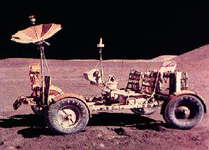 | Lunar rover Credit: NASA |
1966 July 11 - .
- NASA leaders make several significant program decisions affecting AAP and post-Apollo development planning. - .
Nation: USA.
Spacecraft: Apollo ATM,
Apollo LM Shelter,
Apollo LM Truck,
Apollo LRV,
Skylab.
NASA leaders make several significant program decisions affecting AAP and post-Apollo development planning. Meeting at Headquarters, Deputy Administrator Robert C. Seamans, Jr., Associate Administrator for Manned Space Flight George E. Mueller, and Associate Administrator for Space Science and Applications Homer E. Newell made several significant program decisions affecting AAP and post-Apollo development planning in general: MSFC would be the lead Center for developing the ATM and would be responsible for all astronomy experiments. MSFC would be the lead Center for 'lunar engineering'-i.e., design and development of lunar exploration vehicles (including surface modules, supply trucks, and roving vehicles). MSC would have responsibility for Earth resources and lunar scientific experiments.
1969 January 15 - .
- Guidelines for Apollo missions after first landing - .
Nation: USA.
Program: Apollo.
Spacecraft: Apollo LRV.
The Apollo Program Director expressed concern to the Director of MSC over the lack of guidelines of sufficient scope and depth for the lunar missions that would be flown after the first lunar landing and before the proposed lunar exploration program tentatively scheduled to begin in 1973. He asked each of the manned space flight Centers to appoint a working group to define guidelines and to outline program objectives and content for the period of lunar exploration immediately following the first lunar landing. Areas requiring study were: scientific exploration, mission planning rationale, flight schedules and program impact, and vehicle product improvement.
1969 May 27 - .
- Manned Apollo lunar roving vehicle go-ahead - . Nation: USA. Program: Apollo. Spacecraft: Apollo LRV. MSFC was authorized to proceed with development of a manned lunar roving vehicle for use on the Apollo missions beginning in mid-1971. A meeting was scheduled for June 6 in Washington to establish requirements for development of the vehicle..
1969 June 20 - .
- Requirements for the Apollo lunar roving vehicle (LRV) design - .
Nation: USA.
Related Persons: Kraft.
Program: Apollo.
Spacecraft: Apollo LRV.
Christopher C. Kraft, Jr., MSC Director of Flight Operations, recommended that the following fundamental requirements be considered during the lunar roving vehicle (LRV) design approach: "a. A means of continuous voice communication with one crew member, on or off the LRV to the mother station (LM) and from the mother station to earth, must be provided. b. A simple dead reckoning system should be considered for determining the LRV and crew location at all times in order to provide a safe return of the astronauts to the LM. The accuracy should be sufficient to permit the astronauts to rendezvous with the LM from any point on a sortie. c. The vehicle should be designed so that a telemetry system is not required for operation. However, for crew safety and systems operations, instrumentation may be required."
1969 August 7 - .
- Apollo lunar roving vehicle restricted to a 181-kilogram weight limit - . Nation: USA. Program: Apollo. Spacecraft: Apollo LRV. MSFC-NASA Hq. correspondence emphasized the need to restrict the lunar roving vehicle to a 181-kilogram weight limit. If necessary, range and speed would be traded off to retain this weight limit..
1969 August 7 - .
- Modes for future Apollo lunar surface exploration - .
Nation: USA.
Related Persons: Aldrin,
Armstrong,
McDivitt.
Program: Apollo.
Spacecraft: Apollo LRV.
George Low, James McDivitt, Neil Armstrong, and Edwin Aldrin discussed lunar exploration that could be carried out by astronauts walking in spacesuits or riding roving vehicles. The following conclusions were reached: "a. A possible mode of exploration would be to walk 1 hour (3 to 5 miles (5 to 8 kilometers)) to an exploration site; spend 1 to 2 hours at that site; and then return to the LM. b. It would be easy to carry anything that need be carried, provided that it did not require the hands for the purpose. c. A roving vehicle might work if it had extremely large wheels. There appeared to be no significant advantage of using the presently conceived roving vehicle instead of walking. d. All extravehicular excursions should be carried out by two men at a time. e. Excursions should not be carried out beyond the radius of ground communications."
1969 August 18 - .
- Apollo Lunar Roving Vehicle Task Team reconstituted as the Lunar Mobility Task Team - .
Nation: USA.
Program: Apollo.
Spacecraft: Apollo LRV.
The Lunar Roving Vehicle Task Team, which had been established at MSFC on April 7, was reconstituted as the Lunar Mobility Task Team. Its function would be to direct and coordinate MSFC efforts to conceive, design, and develop various modes of lunar transportation systems.
1969 August 26 - .
- Primary batteries should be used to power the Apollo lunar roving vehicle - .
Nation: USA.
Program: Apollo.
Spacecraft: Apollo LRV,
LM Electrical.
In response to a query from MSFC, MSC took the position that primary batteries as opposed to secondary (rechargeable batteries) should be used to power the lunar roving vehicle. Concern was expressed that a solar array recharge assembly would introduce an extra complexity into the LM payload packaging and the roving vehicle servicing requirements and would contribute to a loss in effective EVA time because astronauts would need time to deploy the solar array and connect it to the rover.
1969 October 28 - .
- Apollo lunar roving vehicle (LRV) contract awarded to the Boeing - .
Nation: USA.
Program: Apollo.
Spacecraft: Apollo LRV.
A lunar roving vehicle (LRV) cost-plus-incentive-fee contract was awarded to the Boeing Co. LRV-1 was scheduled for delivery on April 1, 1971, leaving only 17 months for vehicle development, production, and tests. The LRV project was managed at MSFC by Saverio F. Morea as a project within the Saturn Program Office. The Boeing Company would manage the LRV project in Huntsville, Ala., under Henry Kudish. General Motors Corp. AC Electronics Defense Research Laboratories in Santa Barbara, Calif., would furnish the mobility system (wheels, motors, and suspension). The Boeing Go. in Seattle, Wash., would furnish the electronics and navigation system. Vehicle testing would take place at the Boeing facility in Kent, Wash., and the chassis manufacturing and overall assembly would take place at the Boeing facility in Huntsville, Ala.
1969 November 6 - .
- Concern over weight growth of the Apollo lunar roving vehicle - . Nation: USA. Program: Apollo. Spacecraft: Apollo LRV. In an exchange of correspondence between MSFC and MSC concern was expressed over the weight growth of the lunar roving vehicle (LRV) and its payload. As a result, a recommendation was made that MSFC manage the weight of the LRV and MSC the payload weight..
1969 December 1 - .
- Requirement for a simple lightweight Apollo lunar roving vehicle guidance and navigation system - .
Nation: USA.
Program: Apollo.
Flight: Apollo 12.
Spacecraft: Apollo LRV,
LM Communications,
LM Guidance,
LM Weight.
The MSC Flight Crew Operations Directorate submitted its requirement for a simple lightweight Rover (lunar roving vehicle) guidance and navigation system that would provide the following displayed information to the crew: vehicle heading and heading to the LM, speed in kilometers per hour, total distance traveled in kilometers, and distance to the LM. Additional Details: here....
1969 December 16-18 - .
- Apollo lunar roving vehicle preliminary requirements review - .
Nation: USA.
Program: Apollo.
Spacecraft: Apollo LRV.
A lunar roving vehicle preliminary requirements review was held at MSFC. MSC was asked to review the requirement for a roll bar which it had requested in the interest of astronaut safety. Navigation system requirements as defined by MSC would require changes in the design presented by Boeing. Full-length fenders and effects of dust on radiators, sealed joints, and vision needed to be considered and appropriate measures taken in the vehicle design, the review found.
1970 February 6 - .
- Requirements for Apollo lunar roving vehicle (LRV) established - .
Nation: USA.
Program: Apollo.
Spacecraft: Apollo LRV.
A statement of agreements was reached between NASA Hq. and the Centers covering the requirements for a lunar roving vehicle (LRV). Appropriate portions of the agreements were being incorporated in a revised Apollo Program Specification and in Apollo Program Directive No. 4.
1970 September 11 - .
- Modifications were made to Apollo lunar roving vehicle simulator to eliminate extreme fatigue - .
Nation: USA.
Program: Apollo.
Spacecraft: Apollo LRV.
Modifications were made in MSFC's lunar roving vehicle simulator and the static mockup to eliminate extreme arm and hand fatigue felt by a flight crew member and other test subjects after driving 10 to 15 minutes in LRV simulator evaluation tests. A T-shaped handle was added to the pistol grip; a parking-brake release and a reduced brake-travel distance were incorporated; and a mechanical reverse lockout was added.
1971 February 22 - .
- MSC requested removal of sharp corners from the Apollo lunar roving vehicle (LRV) seat - .
Nation: USA.
Program: Apollo.
Spacecraft: A7L,
Apollo LRV.
MSC requested removal of sharp corners from the lunar roving vehicle (LRV) seat. During a recent series of LRV/EMU (extravehicular mobility unit) tests, a nicking or tearing of the portable life support system thermal cover had been discovered. Observation revealed that the thermal cover was contacting sharp corners on the LRV seats, when the test subject entered and left the vehicle.
1971 March 1 - .
- Automatic deployment system for the Apollo lunar roving vehicle abandoned - .
Nation: USA.
Program: Apollo.
Spacecraft: Apollo LRV.
Because of difficulties during the past several months in developing and qualifying an automatic deployment system for the lunar roving vehicle, the automatic system was abandoned in favor of a manual system. Boeing was directed to stop all further effort on the automatic system.
1971 August 1 - . 11:48 GMT - .
- EVA Apollo 15-3 - . Crew: Irwin, Scott. EVA Duration: 0.30 days. Nation: USA. Related Persons: Irwin, Scott. Program: Apollo. Class: Moon. Type: Manned lunar lander. Flight: Apollo 15. Spacecraft: Apollo LRV. Drove in lunar rover to Hadley Delta..
1971 August 2 - . 08:52 GMT - .
- EVA Apollo 15-4 - . Crew: Irwin, Scott. EVA Duration: 0.20 days. Nation: USA. Related Persons: Irwin, Scott. Program: Apollo. Class: Moon. Type: Manned lunar lander. Flight: Apollo 15. Spacecraft: Apollo LRV. Drove in lunar rover to Hadley Rille..
1971 November 18 - .
- Detailed assessment of the lunar roving vehicle (LRV) used on the Apollo 15 mission - .
Nation: USA.
Program: Apollo.
Flight: Apollo 15.
Spacecraft: Apollo LRV.
A detailed objective assessment of the lunar roving vehicle (LRV) used on the Apollo 15 mission indicated:
- The LRV was successfully deployed, with minor problems. . Additional Details: here....
1972 April 22 - . 16:33 GMT - .- EVA Apollo 16-2 - . Crew: Duke, Young. EVA Duration: 0.31 days. Nation: USA. Related Persons: Duke, Young. Program: Apollo. Class: Moon. Type: Manned lunar lander. Flight: Apollo 16. Spacecraft: Apollo LRV. Drove in lunar rover to Stone Mountain..
1972 April 23 - . 15:25 GMT - .- EVA Apollo 16-3 - . Crew: Duke, Young. EVA Duration: 0.24 days. Nation: USA. Related Persons: Duke, Young. Program: Apollo. Class: Moon. Type: Manned lunar lander. Flight: Apollo 16. Spacecraft: Apollo LRV. Drove in lunar rover to North Ray crater..
1972 December 13 - . 23:28 GMT - .- EVA Apollo 17-2 - . Crew: Cernan, Schmitt. EVA Duration: 0.32 days. Nation: USA. Related Persons: Cernan, Schmitt. Program: Apollo. Class: Moon. Type: Manned lunar lander. Flight: Apollo 17. Spacecraft: Apollo LRV. Drove in lunar rover to South Massif..
1972 December 14 - . 22:25 GMT - .- EVA Apollo 17-3 - . Crew: Cernan, Schmitt. EVA Duration: 0.30 days. Nation: USA. Related Persons: Cernan, Schmitt. Program: Apollo. Class: Moon. Type: Manned lunar lander. Flight: Apollo 17. Spacecraft: Apollo LRV. Drove in lunar rover to North Massif..
Back to top of page
Home - Search - Browse - Alphabetic Index: 0- 1- 2- 3- 4- 5- 6- 7- 8- 9
A- B- C- D- E- F- G- H- I- J- K- L- M- N- O- P- Q- R- S- T- U- V- W- X- Y- Z
© 1997-2019 Mark Wade - Contact
© / Conditions for Use