
Home - Search - Browse - Alphabetic Index: 0- 1- 2- 3- 4- 5- 6- 7- 8- 9
A- B- C- D- E- F- G- H- I- J- K- L- M- N- O- P- Q- R- S- T- U- V- W- X- Y- Z
von Braun concept vehicle
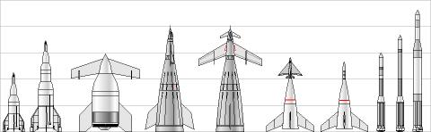
Von Braun Designs
Von Braun designs. From left: A11, 1946; A12; Marsprojekt, 1948; Colliers, 1952; Mars, 1956; Super-Jupiter, 1957; Saturn I and Saturn II for Project Horizon, 1958.
Credit: © Mark Wade
AKA: Von Braun.
The novel was not published until the 21st Century. But Von Braun used the calculations as the basis for a lecture at the First Symposium on Spaceflight held at the Hayden Planetarium in New York on Columbus Day, 1951. Von Braun's concepts, illustrated by magnificent Chesley Bonestell paintings, were made available to a large public with the publication of a series of articles in Collier's magazine beginning in February 1952. This was subsequently released as a book, 'Across the Space Frontier', in 1953. Refined designs were presented in 1956 in 'The Exploration of Mars' and reached an audience of 42 million Americans in a series of programs televised on the Walt Disney show. Von Braun's concepts were known to a wider audience than any other of the period. No other series of articles, books, and programs did more to popularize the idea of manned space travel before Sputnik.
Each subsequent Von Braun design in this series seemed more refined and smaller. This is often cited as a demonstration of the improvements in rocket technology during the 1950's. Von Braun himself, in the preface to his 1948 novel appendix, published in the US as 'The Mars Project' in 1962, compared the performance of his 1948 design with the pending Saturn V.
But detailed examination of the designs show this was all simply a misconception. The 1948 design already made assumptions regarding future rocket engine performance that were not realized until the 1960's. The 1952 Collier's design used the performance and mass figures calculated in 1948, although the design was slenderized to make it more visually appealing. In doing so critical design figures simply no longer applied to the 'new' version. The 1956 'high performance design' simply divided the 1948 figures by five -- the higher payload delivered was simply a result of having dedicated cargo or manned glider payloads, instead of delivering the payload from the cargo bay of a heavy manned glider. So in fact the initial calculations were quite optimistic, and all of the subsequent designs used the same figures.
Let's examine the 1948 calculations in detail, and track how they were misused in the following years.
What Came Before
In the early days in Peenemuende, Von Braun's team considered using the A4 (V-2) rocket then under development as the basis for multi-stage rockets. Design of the two stage A9/A10 began in 1940 and first flight would have been in 1946. Work on the A9/A10 was prohibited after 1943 when all efforts were to be spent on perfection and production of the A4 as a weapon-in-being. Von Braun managed to continue some development and flight tests of the A9 under the cover name of A4b (i.e. a modification of the A4, and therefore a production-related project). In late 1944 work on the A9/A10 resumed under the code name Projekt Amerika, but no significant hardware development was possible after the last test of the A4b in January 1945.
During the course of development, the vehicle evolved. The first stage, the A10, was first to have used a multi-chamber design: a cluster of 6 A4 combustion chambers feeding into a single expansion nozzle. Later a massive single chamber/single nozzle engine was planned. Test stands were built at Peenemuende for firings of the 200 metric ton thrust engine.
The next stage would be the A9/A10/A11. A drawing made for the Army in Texas in 1946 illustrates the design. The A11 stage appears to use six of the A-10 engines. The A10 is nested within the A11 propellant tank, as was the A9 in the A10. The A9 was winged, indicating a gliding recovery or bombing mission. To achieve orbit, either a small kick stage would be needed, or the A9 would have to be significantly lightened compared to the standard version. In any case a payload of only a few 100 kg could be orbited.
The full orbital vehicle would use the A12 stage, concerning which virtually no details have emerged. Assuming it would have followed the sizing of the other stages, it would have used 50 of the 200 metric ton engines, and have been capable of boosting over 10 metric tons of payload into orbit.
Although the early drawings of the A10 engine seem to indicate it used the same benign liquid oxygen/alcohol propellants as the V-2, post-war research by Peenemuende team members in France seem to indicate that there was an intention to move to nitric acid/hydrazine propellants. These were corrosive and toxic, but self-igniting and could be stored and loaded at ambient temperatures -- no handling of cryogenics was required.
The 1948 Design
The Engines
Von Braun selected nitric acid/hydrazine propellants, perhaps as a result of the same Peenemuende research that influenced the French team. He very conservatively used a combustion chamber pressure of 15 atmospheres (as in the V-2 engine). Ideal engine performance for each stage was based on combustion chemistry and gas dynamics calculations. The nozzle expansion ratio differed for each stage, so 'based on experience' Von Braun allowed for expected efficiency losses of 5%, 7%, and 10% on the first, second, and third stages. Total nozzle exit area for each stage was calculated, but no particular detailed engine design was presented. However the height of the engine nozzles was indicated for vehicle sizing.
Specific impulse and thrust for the engines was not expressed in common modern terms, which causes some confusion in the literature. The figures given are the specific impulse at the condition of the ambient atmospheric pressure equaling the nozzle exit pressure. The figures adjusted to vacuum and sea-level specific impulse terms indicate the upper stage versions of the engines would have a specific impulse of 297 seconds, a very respectable value not achieved in flight for a storable propellant engine until 1962.
The nitric acid/hydrazine propellant combination used was found not to be practical without additives. These were developed during the course of the 1950's. But by 1962 nitric acids were replaced as a storable oxidizer by nitrogen tetroxide. Furthermore, in comparison with Von Braun's 15 atmosphere assumption, by 1962 chamber pressures of 40 atmospheres had routinely been achieved, allowing higher expansion ratios (and higher performances) for first-stage engines.
Von Braun used a constant thrust/weight value of 69:1 in calculating the engine mass for all stages. In fact this would be nearly met on the next US large engine design after the V-2, the Redstone. Von Braun's engine used a separate propellant (hydrogen peroxide) to drive the engine pumps. This was the practice used on the V-2, and in Russia was continued even in the R-7 ICBM (which still flies today as the Soyuz launch vehicle). But thereafter the US and Russia moved quickly to turbopumps driven by the same propellants used in the same engine.
The 1948 calculations assumed the exhaust nozzle was in the shape of a continuous annular ring around the central parachute container in the first and second stages. The nozzle completely occupied the base of the third stage. The concept almost presages the aerospike engine designs of the 1960's. It may have been a continuation of the V-2 philosophy of having many combustion chambers feed a single nozzle. It may have been that this was just a means for roughly sizing the base of the launch vehicle.
In the 1952 Collier's series the number of engines per stage were indicated, allowing their mass, diameter and thrust to be allocated. However it must be noted that these diameters cannot be reconciled with the geometry of either the 1948 or 1952 stage designs! Nevertheless it is interesting to compare the figures calculated by Von Braun for his engines with the actual figures achieved for the Titan 2 ICBM engines, the only US storable propellant engines of this size ever developed, first flown in 1962:
| Parameter | Von Braun, 1948 | Titan 2, 1962 |
| Engine | Booster | LR-87-5 |
| Thrust(vac)-kN | 2770 | 1097 |
| Mass Engine-kg | 4098 | 739 |
| Thrust/Weight | 69 | 151 |
| Diameter-m | 2.36 | 1.14 |
| Length-m | 6.00 | 3.13 |
| Chamber Pressure-bar | 15 | 53 |
| Area Ratio | 3.77 | 8.00 |
| Propellants | Nitric acid/Hydrazine | N2O4/Aero-50 |
| Isp-sec | 257 | 297 |
| Isp (sea level)-sec | 217 | 259 |
| Burn time-sec | 84 | 155 |
| Engine | Second Stage | LR-91-7 |
| Thrust(vac)-kN | 479 | 445 |
| Mass Engine-kg | 706 | 565 |
| Thrust/Weight | 69 | 80 |
| Diameter-m | 3.35 | 1.68 |
| Length-m | 4.5 | 2.8 |
| Chamber Pressure-bar | 15.0 | 56.2 |
| Area Ratio | 50.2 | 49.2 |
| Propellants | Nitric acid/Hydrazine | N2O4/Aero-50 |
| Isp-sec | 298 | 315 |
| Burn time-sec | 124 | 175 |
The Structure
When considering Von Braun's estimates for the structural weight of his rocket, he arrived at values near those achieved in the late 1960's for the Saturn and N1 vehicles in the US and Russia. His values look larger at first, but they include the mass of recovery equipment (parachutes and soft-landing retrorockets) that amounted to 18% and 11% of the empty weights of the first and second stages respectively. Deducting these amounts, and the hydrogen peroxide consumed during the ascent, and it is apparent that Von Braun calculated values for the structure of his launch vehicles essentially equivalent to those for the only vehicles of those size built in the US and Russian in the late 1960's:
| Structure | Von Braun 1962 | Saturn V 1968 | N1 1969 |
| Stage | First Stage | S-IC | N1 Block A |
| Total Propellants | 4,718,000 | 2,150,999 | 1,750,000 |
| Stage Fraction | 5.15% | 4.34% | 5.15% |
| Stage | Second Stage | S-IB | N1 Block B |
| Total Propellants | 720,600 | 407,054 | 505,000 |
| Stage Fraction | 6.86% | 8.97% | 8.90% |
Third-Stage Re-entry Vehicle
The third stage itself made a long re-entry glide for 22,000 km from atmosphere entry interface at 80 km -- 55% of the earth's circumference! During this time the glider experienced a peak deceleration of 0.45 G and a peak airframe temperature of 1005 deg K. The airframe of the glider was seen as reaching a thermal equilibrium during the long glide, where it could re-radiate heat as quickly as it was absorbed. Based on this Von Braun concluded the glider could be built of existing steels (although he admitted that 'latest information' indicated the peak heating could be 300 deg K higher).
Research during the 1950's showed that the higher value was nearer the truth and that the temperatures at the leading edges of re-entry vehicles far exceeded the theoretical average values calculated in 1948. The Dynasoar design of the early 1960's, the closest analogue to Von Braun's design to reach an advanced stage of development, would have experienced peak nose temperatures of 2140 deg K, with the structure stabilizing at 1255 deg K during an equivalent long-glide re-entry. It was necessary to build the Dynasoar's external skin from coated molybdenum, and the internal structure from Rene-41 nickel alloy. Von Braun's plan to use conventional steel would not have worked. Furthermore, to cool the pilot and payload, it was necessary to encase the cockpit and payload bay in a heavy 'water wall' insulation/cooling system. The lightweight refrigeration system used in Von Braun's calculations would not have been adequate.
The conventional solution for re-entry design became the use of ablative or exotic heat-radiative skin materials, and to get the re-entry accomplished as quickly as possible to avoid heat-soaking the structure. The space shuttle, for example, experiences actual maximum external temperatures of 1800-1250 deg K, lands just 5450 km down-range from an altitude of 80 km, and pulls a maximum of 2 G's during re-entry. The internal structure is nearly completely protected from the heat of re-entry (as long as there is no breach, as on STS-107), and is primarily 2024-T81 aluminum alloy.
However a minority of the technical community continues to advocate Von Braun's long-glide, high-lift, re-radiative approach. These included Nonweiler waverider advocates, who proposed to actively cool the sharp, hot leading edge of their designs but claimed the rest of the spacecraft could be built from conventional metal structure. The following compares several designs to show the effect of wing loading on peak and minimum underbelly heating for gliding re-entry vehicles.
| Vehicle | Wing loading kg/sq m | Peak heating deg K | Min underbelly deg K |
| Von Braun 1948 | 73 | >1400 | 1100-1400 |
| RASV 1968 | 85 | 1793 | 923 |
| Black Horse 1996 | 102 | 1640 | |
| DynaSoar 1962 | 158 | 2160 | 1600 |
| Shuttle 1980 | 585 | 1813 | 1253 |
The Recovery Systems
Von Braun's glider was designed to deliver nominally 25 metric tons of cargo, plus 14.5 metric tons of 'excess propellant'. This would be used to assemble the enormous planned Mars expedition - 70 crew aboard ten spacecraft with a mass of 3720 metric tons each!
Since assembly of an expedition of this size would take 950 launches, Von Braun was very concerned to make sure all of the launch vehicle was recoverable and reusable. The first stage would return to earth under a 64.5 m diameter parachute weighing 85 metric tons! Just prior to splashdown 40 metric tons worth of solid rockets would ignite and allow the stage to splashdown at zero velocity 304 km downrange. It would be towed back to the Johnston Island launch site by a tug, refurbished, and reused. The total mass of the recovery provisions amounted to 18% of the stage empty mass. The second stage required a 20.4 diameter chute with a mass of 3.8 metric tons and 4 metric tons of braking rockets. It would be recovered 1459 km down-range and the recovery provisions were 11% of the stage empty mass.
If we delete the recovery provisions and the manned glider provisions from the design, we can calculate that the three stages Von Braun's design could deliver 60 metric tons, or one percent of its lift-off mass, into a 200 km polar orbit. By comparison, the three-stage Titan 3A (with transtage) could deliver 1.33% of its lift-off mass into the same orbit. This again emphasizes the modernity of the design.
The 1952 Version
For the drawings and paintings to illustrate the 1952 Colliers series and subsequent books, the 1948 version was found to be too dumpy and squat to inspire. Therefore, Von Braun, in collaboration with artist Rolf Klep, sketched a much more elegant tapered launch vehicle design. The still somewhat-squat official version became even more stretched and elegant looking in the artist's renderings. This can be contrasted with Von Braun's Redstone, then already in design, which used the uninspiring but efficient cylindrical body that would be the basis of his later Jupiter and Saturn rockets. One can only conclude that Von Braun went along with the artist's desires for a more glamorous-looking rocket ship.
The base diameter of the first stage remained the same, but those of the upper stages were drastically reduced. To make more room for engines in the base, the parachute package was changed from a centrally-located canister to a steel-mesh circular drag brake, stored along the outer fuselage. The engine concept was now changed from an annular nozzle to separate conventional bell-nozzle engines. Since the first stage diameter was the same, and the parachute canister that took up half its diameter was deleted, there was enough room in the first stage for 52 such engines. However there were real problems in using the 1948 calculations for the upper stages.
The second stage diameter was reduced from 20 m to 13.5 m. There was simply not enough base area for the total nozzle area indicated in Von Braun's original calculations. This could have been remedied if the chamber pressure was increased, as was clearly possible by 1952. However that should have resulted in a higher specific impulse, but the 1948 calculations were used 'as-is'. Klep's illustrations showed Redstone-type low-expansion ratio engines, inconsistent with the area ratio calculated in 1948 and needed for the high engine performance.
Similarly, the third stage diameter was reduced from 9.8 m to 5.8 m, with the same logical problem, since in the original calculation the nozzle occupied the entire base of the third stage.
The 1956 Version
By 1956 Von Braun was just months away from the first launch of his Jupiter ballistic missile and sketching what would become the Saturn I launch vehicle. His design group clearly knew that any real launch vehicle would consist of simple cylindrical bodies. Fins had been entirely deleted on the Jupiter and Saturn designs.
However Von Braun, or his collaborator Willy Ley, did not bring their nominal space launch vehicle up to date. The design presented in print and television in 1955-1957 was simply a small-scale version of the 1952 design. The first and second stages were simply reduced to 20% of their former size. The expendable third stage was tiny, equivalent to the Agena stage then under secret development. Its main purpose was to maintain the burn-our velocity of the second stage as calculated in 1948. In this way the 1948 calculations could remain sub-orbital and recoverable. The manned glider became a separate payload, that could be replaced by an 'all cargo' module. The only nod to modernity was that the glider was now delta-winged, a better solution for a vehicle that had to be stable over a wide range of airspeeds.
The Super-Jupiter
The Super Jupiter was Von Braun's actual first government-sponsored study for a large space-launch vehicle. In keeping with technological developments during the 1950's, it would be a cylindrical, unfinned vehicle, using a small number (one to eight) liquid oxygen/kerosene propellant engines. But Von Braun still was concerned that such a large and expensive vehicle be recoverable. As the Super Jupiter evolved into the Saturn I, the recovery provisions would eventually be dropped, and with it the last technical vestige of his original 1946 design.
Von Braun, the N1, and Nova
Some writers have pointed to similarities between the Von Braun 1952 design and the Korolev N1 moon rocket design of ten years later. Both have tapered stages and large numbers of engines clustered in each stage. But the previous analysis shows that the 1952 design was a purely artistic conceit. Internally, the designs were very different. The N1 used spherical propellant tanks, rather than the flat-bulkhead tanks advocated for the Von Braun rocket. Finally, the N1 design can be better traced back to the designs of the German team headed by Groettrup (see the 'Early Russian Ballistic Missiles' family). It is interesting that the flat-bulkhead tanks would emerge again in the General Dynamics Nova GD-F and GD-H designs of 1963 - perhaps another expression of a concept going back to the Von Braun 1948 design...
| Von Braun 1948 German winged orbital launch vehicle. Von Braun's 1948 design for a reusable space launcher was remarkable in its tubby design. This was partly driven by the need for large parachute canisters in the base of the first and second stages, which took up one half of the diameter, with the engines arranged around the periphery. |
| Von Braun 1952 German winged orbital launch vehicle. Von Braun's 1952 design for a reusable space launcher used the same mass and performance calculations done in 1948. However the large parachute canisters were replaced by deployable drag skirts. This allowed the design to be substantially less squat and more elegant than the 1948 version -- but still fatter than the sleek paintings that appeared in print! |
| Von Braun 1956 German winged orbital launch vehicle. In 1956, for the book Exploration of Mars and the Disney television series, the 1952 design was significantly 'down-sized'. The first and second stages were simply reduced to 20% of their former size. A tiny expendable third stage replaced the manned glider. The manned glider itself became a separate payload, that could be replaced by an 'all cargo' module. |
Country: USA.
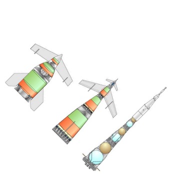 | Von Braun vs N1 Cutaway views of Von Braun 1948, Von Braun 1952, and the Soviet N1 Credit: © Mark Wade |
1950 October 12 - . LV Family: von Braun concept vehicle. Launch Vehicle: Von Braun 1948.
- First Symposium on Space Flight - .
Nation: USA.
Related Persons: Haber,
Ley,
von Braun.
The First Symposium on Space Flight was held at the Hayden Planetarium in New York City. Participants included Wernher von Braun, Joseph Kaplan, Heinz Haber, Willy Ley, Oscar Schachter, and Fred L. Whipple. Among the topics discussed were an orbiting astronomical observatory, problems of survival in space, circumlunar flight, a manned orbiting space station, and the question of sovereignty in outer space.
1952 February 11 - . LV Family: von Braun concept vehicle. Launch Vehicle: Von Braun 1952.
- Collier's Man Will Conquer Space Soon - . Nation: USA. Related Persons: Ley, von Braun. Collier's magazine published papers from First Symposium on Space Flight, under the title "Man Will Conquer Space Soon.". This was an important step in the popularization of the idea of manned space flight..
Back to top of page
Home - Search - Browse - Alphabetic Index: 0- 1- 2- 3- 4- 5- 6- 7- 8- 9
A- B- C- D- E- F- G- H- I- J- K- L- M- N- O- P- Q- R- S- T- U- V- W- X- Y- Z
© 1997-2019 Mark Wade - Contact
© / Conditions for Use