
Home - Search - Browse - Alphabetic Index: 0- 1- 2- 3- 4- 5- 6- 7- 8- 9
A- B- C- D- E- F- G- H- I- J- K- L- M- N- O- P- Q- R- S- T- U- V- W- X- Y- Z
GRACE
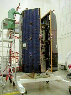 Grace 1 & 2 The two Grace satellites mounted belly-to-belly in the dispenser. |
AKA: ESSP. Status: Operational 2002. First Launch: 2002-03-17. Last Launch: 2002-03-17. Number: 2 . Gross mass: 432 kg (952 lb).
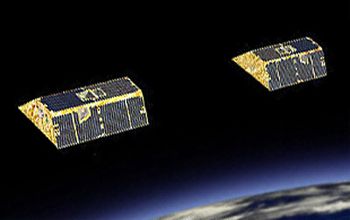
The mission had two identical spacecraft flying about 220 kilometers apart in a polar orbit 500 kilometers above the Earth.
The GRACE mission was selected as the second mission under the NASA Earth System Science Pathfinder (ESSP) Program in May 1997. GRACE would map the Earth's gravity fields by making accurate measurements of the distance between the two co-orbital satellites, using GPS and a microwave ranging system. It would provide scientists from all over the world with an efficient and cost-effective way to map the Earth's gravity fields with unprecedented accuracy. The results from this mission were to yield information about the distribution and flow of mass within the Earth and it's surroundings.
The gravity variations that GRACE would study included: changes due to surface and deep currents in the ocean; runoff and ground water storage on land masses; exchanges between ice sheets or glaciers and the oceans; and variations of mass within the Earth. Another goal of the mission was to create a better profile of the Earth's atmosphere. GRACE would make a contribution to the goals of NASA's Earth Science Enterprise, Earth Observation System (EOS) and global climate change studies.
GRACE was a joint partnership between the National Aeronautics and Space Administration (NASA) in the United States and Deutsche Forschungsanstalt fuer Luft und Raumfahrt (DLR) in Germany. Dr. Byron Tapley of The University of Texas Center for Space Research (UTCSR) was the Principal Investigator (PI), and Dr. Christoph Reigber of the GeoForschungsZentrum (GFZ) Potsdam was the Co-Principal Investigator (Co-PI). Project management and systems engineering activities were carried out by the Jet Propulsion Laboratory.
Mission Systems
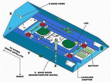
The science instruments were mounted on a CFRP bench in the interior, as were the fuel tanks and the batteries and other satellite sub-systems.
The TT&C activities were carried out using a pyro-deployed S-Band receive and transmit antenna, mounted on a nadir-facing deployable boom. Two back-up zenith antennae, one each for transmitting and receiving, along with the appropriate RF electronics assembly, completed the telemetry and telecommand sub-system.
The CM Trim Assembly consisted of six Mass Trim Mechanisms, associated electronics, and the power and signal harness. Each MTM consisted of a trim mass driven on a nut rotor with a stepper motor. The CMT Assembly was used to center the CG of the satellite at the center of the proof-mass of the accelerometer, during CG calibration maneuvers.
The Thermal Control Sub-System consisted of 64 independent heater circuits, 45 resistors and 30 thermistors for in-flight temperature housekeeping, monitoring and heater control, as well as for on-ground verification testing.
The Power System was responsible for generation, storage, conditioning and distribution of electrical power in accordance with instrument and satellite bus users needs. Electrical energy was generated using a solar array of Globalstar silicon cells, placed on the top and side exterior surface of the satellites. Excess energy was stored in a battery of NiH2 common pressure vessel cells. The power bus delivered unregulated power to all users at the respective user interface.
The Attitude and Orbit Control System (AOCS) consisted of sensors, actuators and software. The sensors included the DSS Coarse Earth Sun Sensor (CESS) for omni-directional, coarse attitude measurement in the initial acquisition, survival and stand-by modes of the satellite. The high precision sensors included the SCA and GPS receiver. An Inertial Reference Unit (IRU), used in survival modes, provided 3-axis rate information. A Foerster Magnetometer was mounted on the deployable boom, to provide additional rate information. The actuators for the AOCS include Cold Gas Assembly and a Magnetorquer. The GN2 reaction control system included two pressure vessels, valves, regulators and filters, along with 12 attitude control thrusters and two orbit control thrusters. Three magnetorquers with linear dipole moments of 30 Am2 complete the set of AOCS actuators.
The On-Board Data Handling (OBDH) System provided processor and software resources, as well as necessary I/O capabilities for AOCS, Power and Thermal Systems operations, including necessary fault detection, isolation and recovery operations.
Key Spacecraft Components:
- K-band Ranging System. Provided precise (within 10 um) measurements of the distance change between the two satellites and thus measured the fluctuations in gravity. Ultra Stable Oscillator. Provided frequency generation for the K-band ranging system.
- S-band Boom. Allowed the satellite to transmit and receive data from surface tracking stations.
- SuperSTAR Accelerometers. Precisely measured the nongravitational accelerations acting on the satellite.
- Star Camera Assembly. Precisely determined two satellites' orientation by tracking them relative to the position of the stars.
- Coarse Earth and Sun Sensor. Provided omnidirectional, reliable and robust, but fairly coarse Earth and Sun tracking. To be used during initial acquisition and when GRACE was operating in "safe mode."
- Center of Mass Trim Assembly. Precisely measured offset between the satellite's center of mass and the "acceleration-proof" mass and adjusts center of mass as needed during flight.
- Black-Jack GPS Receiver and Instrument Processing Unit. Provided digital signal processing; measured the distance change relative to the GPS satellite constellation; and provided secondary atmospheric occultation experiments.
- Laser Retro-Reflective Assembly. Provided measurements of the GRACE satellite orbits relative to terrestrial tracking networks.
- Globalstar Silicon Solar Cell Arrays. Covered the outer shell of the spacecraft and generated power.
- Three-axis Stabilized Attitude Control System. Used star camera and gyro sensors and a cold-gas nitrogen thruster system, with magnetorquers for fine corrections of spacecraft position.
- 1750-A Microprocessor for Flight Computer. Performed calculations for attitude adjustment and telemetry processing.
More at: GRACE.
Family: Earth, Earth geodetic sat. Country: USA. Launch Vehicles: UR-100N, Rokot. Launch Sites: Plesetsk, Plesetsk LC133/1. Agency: NASA, DLR, Friedrichshafen. Bibliography: 2, 3753, 3754, 3755, 548, 552, 554, 6539, 12518.
 | GRACE 1 Credit: Manufacturer Image |
 | GRACE-FO Credit: Manufacturer Image |
 | Grace |
2002 March 17 - . 09:21 GMT - . Launch Site: Plesetsk. Launch Complex: Plesetsk LC133/1. Launch Pad: LC133/pad?. LV Family: UR-100N. Launch Vehicle: Rokot.
- GRACE 1 - .
Payload: ESSP-2A, 'Tom'. Mass: 432 kg (952 lb). Nation: Germany.
Agency: DLR,
NASA.
Manufacturer: Friedrichshafen.
Class: Earth.
Type: Seismology satellite. Spacecraft Bus: CHAMP.
Spacecraft: GRACE.
Decay Date: 2018-03-10 . USAF Sat Cat: 27391 . COSPAR: 2002-012A. Apogee: 464 km (288 mi). Perigee: 446 km (277 mi). Inclination: 89.00 deg. Period: 93.70 min.
First commercial flight of Rokot booster. Launch delayed from November 23-30, 2001, February 27, March 15 and 16. The Briz-KM upper stage ignited 5 minutes after launch and after a ten minute burn reached a 300 x 500 km orbit at about 0936 UTC. A second burn at 1042 UTC placed the satellites in a 483 x 506 km x 89 deg orbit; the two GRACE gravimetric satellites separated from the dispenser at 1047 UTC. A third Briz burn then lowered the rocket stage orbit to 146 x 487 km x 89 deg so that it would reenter quickly.
- GRACE 2 - . Mass: 432 kg (952 lb). Nation: Germany. Agency: DLR, NASA. Manufacturer: Friedrichshafen. Class: Earth. Type: Seismology satellite. Spacecraft Bus: CHAMP. Spacecraft: GRACE. Decay Date: 2017-12-24 . USAF Sat Cat: 27392 . COSPAR: 2002-012B. Apogee: 464 km (288 mi). Perigee: 445 km (276 mi). Inclination: 89.00 deg. Period: 93.70 min. Gravimetry, Climatology first commercial flight delayed from November23-30, 2001, February27, March15 and 16. .
Back to top of page
Home - Search - Browse - Alphabetic Index: 0- 1- 2- 3- 4- 5- 6- 7- 8- 9
A- B- C- D- E- F- G- H- I- J- K- L- M- N- O- P- Q- R- S- T- U- V- W- X- Y- Z
© 1997-2019 Mark Wade - Contact
© / Conditions for Use