
Home - Search - Browse - Alphabetic Index: 0- 1- 2- 3- 4- 5- 6- 7- 8- 9
A- B- C- D- E- F- G- H- I- J- K- L- M- N- O- P- Q- R- S- T- U- V- W- X- Y- Z
Martlet 4
 Martlet 4 The original Martlet 4 design, with the sub-calibre first stage and ACM. |
Status: Development ended 1966. Payload: 23 kg (50 lb). Thrust: 47.40 kN (10,656 lbf). Gross mass: 1,300 kg (2,800 lb). Height: 8.54 m (28.01 ft). Diameter: 0.42 m (1.37 ft). Apogee: 425 km (264 mi).
MARTLET 4
The Martlet 4 was a full-bore, multi-stage, gun-launchable rocket. Although the Martlet 4 could have been used to launch heavy sub-orbital payloads, it was primarily designed as a satellite launcher.
THE HARP ORBITAL PROGRAM
The HARP orbital program was not part of the original HARP mandate of exploring the upper atmosphere. It was not until 1964, when agreements between the Canadian and the US governments permitted stable funding over the following three years, that HARP was able to seriously consider an orbital program. Even though the technical aspects of the Martlet 4 development progressed relatively smoothly, the HARP orbital program met with criticism from its inception, with much of it being unfounded, uninformed and undue. To defend itself the HARP staff applied considerable efforts to rebut these often insidious attacks, which came steadily over a period of years from certain quarters. This criticism, along with external political pressures and competing research programs, led to repeated funding delays during the development of the Martlet 4. Even the extraordinary technical efforts of the HARP staff could not overcome this external pressure. With these considerations in mind it was not surprising that HARP was not able to successfully gun-launch a satellite, although they were more then successful in proving the feasibility of a low-cost, gun-launched satellite system.
During the last year of the HARP program, when it became clear that further funding was not forthcoming, and that the goals of the Martlet 4 program were not to be realized, full efforts were diverted to developing a Martlet 2G-2 orbital vehicle (GLO-1A). It was felt that if a satellite - any satellite, no matter now small - could be successfully gun-launched, that it then would be possible to encourage further funding, either public or private, which would permit the orbital goals of the HARP program to be realized. Unfortunately time and fate were against HARP and the project was closed down on June 30 1967, only a few months before an orbital 2G-2 could be flown.
The Martlet 4 program began in the spring of 1965 with extensive parametric studies which showed that meaningful payloads could be launched into low Earth orbit from the 16 inch L86 HARP gun on the Barbados flight range using a full bore, 3 stage rocket vehicle.
MARTLET 4 VEHICLE GENERAL DESCRIPTION
The original Martlet 4 design parameters called for a vehicle with three solid rocket stages able to launch a payload between 25 and 50 pounds into low earth orbit from the 16 inch L86 gun on Barbados with an all up shot weight on the order of 2000 pounds
The original Martlet 4 vehicle was only 29 feet long, which was quite small for a satellite launcher, and puts it in the size category of a typical sounding rocket. The many advantages of gun-launching allowed the Martlet 4 to be capable of orbiting a small satellite while retaining launch costs similar to that of a sounding rocket.
The first stage of the Martlet 4 (Martlet 4A stage) was a solid rocket motor 156 inches long with a fuel weight of 1620 pounds and an all up weight 1960 pounds Attached to the base of the first stage were a set of 6 flip-out fins. These fins were folded flat and in-line with the vehicle's body while the vehicle was in the gun barrel. They popped out to a 45 degree angle at muzzle exit. The fins were chamfered to allow aerodynamic forces to create a vehicle spin rate of about 4.5 to 5.5 rotations per second, providing gyroscopic stability for the remainder of the flight. The fixed geometry of the gun barrel and the very stable and predictable flight path of all gun-launch vehicles eliminated the need for any guidance corrections prior to the Martlet 4's first stage rocket motor burn.
A slightly modified version of the Martlet 4A stage was also intended for use as the Martlet 3D vehicle. The Martlet 4A stage holds the worlds record for the largest rocket motor launched from a gun.
The second stage of the Martlet 4 (Martlet 4B stage) was a solid rocket motor 52 inches long with a fuel weight of 400 pounds and an all up weight of 500 pounds . The Martlet 4B stage design was little more then a shortened Martlet 4A stage that was optimized for its role.
Between the second and third stages was the Attitude Control Module. After the first stage had burned out and separated from the rest of the vehicle, the Attitude Control Module was used reorient the vehicle to pre-programmed pitch and yaw angles relative to the horizon, prior to the ignition of the second and the third rocket stages. Immediately prior to second stage ignition the module was deactivated and the second stage thrust occurs without active guidance. After the second stage had burned out the empty stage was retained and the Attitude Control Module was reactivated so that the vehicle could be properly orientated for third stage thrust. Just prior to third stage ignition the second stage, with the Attitude Control Module attached, was released and the third stage thrust also occurred with out active guidance.
The third stage of the Martlet 4 (Martlet 4C stage) was a solid rocket motor 48 inches long with a fuel weight of 160 pounds and an all up weight of 200 pounds . Early versions of Martlet 4C stage design called for a sub-caliber rocket motor some 12 inches in diameter but this concept was soon abandoned and all subsequent versions use a full-bore16 inches diameter motor
The satellite insert motor was considered the fourth stage of the Martlet 4. This motor was fixed to the satellite payload and its nozzle pointed in the direction of travel during launch. As the vehicle was gyroscopically stabilised by the flip-out fins immediately after launch the satellite retained its relative orientation throughout the launch sequence and was pointing in the proper direction at the first apogee when the insert burn occurred.
The nose cone was a simple straight cone and allowed payloads of up to 48 inches in length to be carried.
MARTLET 4 MISSION PROFILE
The Martlet 4 mission began with the preparation and pre-flight testing of the gun-launcher and the launch vehicle. The simplicity and the small size of this launch system greatly reduced the preparation time for the gun-launcher and the vehicle to only a few hours. This was particularly noteworthy when comparing the Martlet 4 to a conventional satellite launching rocket with a similar capacity which could require weeks or even months to prepare. The fast preparation time for a gun-launched orbital flight was one of the greatest advantages of a gun-launched satellite system and it would not have been uncommon for the HARP launch facility on Barbados to have been capable of launching four to six Martlet 4 vehicles per DAY when required. As well, due to the very high gun-launch velocities, Martlet 4's could have been launched in adverse weather conditions that would have prevented a rocket-based satellite launcher from flying.
After the preparations were complete the Martlet 4 vehicle and the gun propellant were loaded into the gun-launcher and the gun was elevated to the launch angle. With the gun loaded and ready there was a short countdown to insure that all systems were still "go" and the down range danger zone was clear. The firing of the gun was a simple mater of sending an electrical signal to the gun-launcher at the appropriate moment to ignite the gun propellant. The actual gun-launch cycle took only a fraction of a second with the Martlet 4 leaving the launcher at about 1370m/s. Immediately upon leaving the gun-launcher the flip-out fins pop into position. Aerodynamic forces acting on the fins spun up the vehicle, providing gyroscopic stability throughout the remainder of the flight.
After gun-launch the vehicle coasted upward and down range for 45 seconds prior to first stage ignition. This First Coast Phase allows the vehicle to rise to an altitude of 26.5 km were the air had thinned to a fraction of sea level pressure. The delay in the first stage ignition also allowed the flight controllers ample opportunity to determine if the vehicle was in stable flight and if all of the primary systems were operating properly prior to allowing first stage powered flight. During the First Coast Phase air drag and gravity will have reduced the vehicles velocity from 1370 m/s at launch to about 1072 m/s.
First stage ignition occurs at T+45 seconds into the flight. The first stage burn would have taken about 20 seconds and increased the vehicle's velocity to 3520 m/s. At burnout the vehicle's altitude was 40 km. Immediately after first stage burnout the stage separated from the rest of the Martlet 4 and then re-entered the atmosphere and impacted in the ocean.
No active guidance was used between the gun-launching and the first stage's powered flight. One of the prime technical advantages of a gun-launcher was that the fixed geometry of the gun barrel and very high launch velocities allow for highly accurate predictions of a gun-launched vehicle's flight path. The flight path of a gun-launched vehicle was so predictable, in fact, that there was no need for active guidance prior to the first stage burn of any gun-launched rocket. This held true for multi-stage vehicles such as a Martlet 4 and for single-stage rocket-assisted vehicles such as the Martlet 3D and 3E.
The second stage ignition was delayed until T+65 seconds. During the 10 second delay between the first and second stage burns the Attitude Control Module was activated. Any corrections to the vehicles attitude, relative to Earth's horizon, were made. The Attitude Control Module was then deactivated just prior to second stage ignition. The second stage burn was to have taken about 20 seconds and increased the vehicle's velocity to 5790 m/s and its altitude to 78.4 km. Following second stage burnout the second stage was NOT separated but was retained until just prior to third stage ignition.
The third stage ignition occurred at T+490 seconds into the flight. Between second stage burnout and third ignition was a Third Coast Phase of 395 seconds. During this coast phase the Attitude Control Module was activated periodically and allowed to reorient the vehicle to insure the proper alignment for the third stage burn. The Third Coast Phase also allowed time for the vehicle to gain significant altitude and to travel far down range on its sub-orbital trajectory.
Immediately prior to third stage ignition the Attitude Control Module was deactivated and the burned-out second stage, with the Attitude Control Module attached, was jettisoned from the remainder of the vehicle.
By T+509 seconds the third stage had burned out. By this time the vehicle's velocity was 7653 m/s and its altitude was 428 km. After the burnout the third stage was separated to re-enter and burn up in the atmosphere.
The intended final orbit was nearly circular with a perigee of about 425 km and an apogee of about 430 km. Before the satellite was able to settle into its final orbit a fourth and final rocket motor burn was required. The orbital insert motor was incorporated into the satellite and was not ejected after use. At third stage burnout the orbital insertion motor was orientated with its nozzle pointing in the direction of travel. As the gyroscopically stabilised satellite came around the Earth it was pointing in the appropriate direction for the orbital injection burn. The orbital injection burn occurred at the first apogee some 45 minutes after the vehicle was gun-launched.
The accuracy of the final orbit was highly dependent on the timing of the orbital injection burn with greater accuracy being achieved by the command firing of the injection burn by ground controllers.
ATTITUDE CONTROL MODULE
The attitude control module for the Martlet 4 vehicle was a remarkable piece of engineering. Consider for a moment the state of the available technologies in 1965 when work on this critical component began. In 1965 solid state electronics was still an infant technology with few complicated integrated circuit chips available and no significant CPU's. The gyroscopes typically used for missile and rocket guidance control were not suitable for use in a gun-launched vehicle. The Martlet 4 project engineers were faced with the daunting task of developing an entirely new type of guidance system which would be suitable for this unique launch application.
From the beginning of the HARP program their use of big guns to launch payloads into space attracted great interest from a wide variety of specialized industries. To solve the problem of the Martlet 4 guidance system the development program was expanded to include interested industrial contributors. The primary HARP development group (McGill University, the US Army's Ballistics Research Laboratory, and the Harry Diamond Laboratory) designated Aviation Electric Limited of Montreal, Canada, as the prime contractor to develop a gun-launchable guidance system suitable for the Martlet 4 mission profile.
Almost from the onset of the program it was recognized that the delicate mechanical gyroscopes typically used for rocket guidance at the time were unsuitable for the high g-loads of gun-launching. The foremost goal of the Attitude Control Module research team was to create new methods of determining the pitch, yaw and roll rate of the vehicle.
The final concept for the Martlet 4 Attitude Control System was simple yet effective. The Martlet 4's Attitude Control System was primarily an analogue unit that gathered information from several sensors, compared it to pre-set reference angles and then fired cold gas thrusters at the appropriate moment to correct the vehicles pitch and yaw angles for the next motor burn. During flight this module would be activated periodically to let the system correct the vehicle's attitude and then turned off to conserve propellant as the vehicle coasted to the next rocket motor ignition event.
The first piece of necessary information acquired by the system was the exact spin rate of the vehicle. The spin rate sensor was a simple accelerometer developed by Aviation Electric Limited. As the vehicle rotated in flight the sensor determined the roll rate and provided a reference pulse for the other subsystems.
The pitch angle of the vehicle was determined by two infrared sensors. Actually miniature infrared telescopes, the sensors looked out the side of the Attitude Control Module, one perpendicular to the vehicle's axis, and the other at an angle. On each rotation of the vehicle the "Earth Pulse Width Comparator" would analyze the signals from both sensors and a pitch angle relative to the local horizon was generated.
The yaw angle of the vehicle was determined by sun sensors. The sun height sensor was mounted looking out and forward of the Attitude Control Module. On each rotation the "Sun Pulse Height Comparator" circuit read the information from the sun height sensors and determined the pitch angle of the vehicle relative to the sun. This comparator obviously required a pre-programmed sun angle relative to the time of day the vehicle was launched to serve as a reference for the proper yaw angles to be determined.
These three pieces of information were fed in to the "Switching Logic and Nozzle Firing" circuit. The Switching Logic module compares the sensor information and determined if there was a misalignment in the vehicle's attitude. When a misalignment was identified, the system determined which thrusters to fire and the timing of the thruster pulse to correct the vehicle's attitude for the next rocket motor burn.
Once the operating principles of the Attitude Control Module were established the development and flight testing of the system's components began. In 1965, when this critical component of the Martlet 4 was under development, the HARP project's engineers already had many years of experience in the design and development of gun safe electronics. Therefore the development of the guidance system's components proceeded relatively smoothly. The primary components of the Attitude Control Module were assembled and bench tested, and then they were flight-tested to insure that they could withstand the stresses of gun-launching.
The flight testing of the components for the Attitude Control Module was carried out primarily from the HARP test range in Highwater, Quebec. To increase turn around time and reduce costs much of the flight testing was carried out using the small 155 mm (6.25 inch ) smooth bored guns. The components were packaged into full-bore slugs and fired either vertically, with recovery via parachute, or horizontally, with recovery using the over-the-ice technique.
Components for the Attitude Control Module were gun-launch tested to proof loads of 10,000 g's which was about twice that experienced by the Martlet 4 during launch and provided a considerable safety factor. The launch forces experienced by the Martlet 4 were actually fairly soft for a gun-launch vehicle considering the some HARP vehicles regularly carried telemetry packages after launch loads in the range of 50,000 g's.
To be considered qualified for this application components would be gun-launched, recovered and compared to the pre-launch calibrations to determine if any gun-launch acceleration-related changes had occurred. Typical components would be test launched several times before the design was considered flight qualified to insure a high degree of system reliability. Once the primary components of the Attitude Control Module were individually proven, entire ACM assemblies were packaged in a 6.25 inch airframe and flown to insure the assembly would function in flight as a complete unit.
With the development of the Martlet 4 rocket stages incomplete it was not possible to test the Attitude Control Module under actual flight conditions. It was considered that the testing procedures for this assembly insured a high degree of confidence in the Attitude Control Modules reliability and no major concerns during actual flight conditions were anticipated.
DEVELOPMENT OF THE MARTLET 4 PROPULSION STAGES
The development of the Martlet 4 rocket stages was a unique endeavor in the history of rocketry and it was the first time that anyone had attempted to develop such a large multi-stage gun-launchable rocket vehicle. The Martlet 4's development began soon after the developmental flights of the Martlet 2A and 2B and closely followed the successes of the 7 inch full bore Martlet 3E development program. The development of the Martlet 4 rocket stages, and that of other Martlet 4 subsystems, ran in parallel to the development of the Attitude Control Module.
The original design concept for the Martlet 4 first stage (Martlet 4A) consisted of welded steal, sheet metal, motor case with threaded end enclosures. The motor case was slightly sub caliber and used narrow brass bore riders at either end and a thin rolled metal external discarding solid sabot between the bore riders as a ware surface. The all up weight of the motor was 1160 pounds with a fuel weight of 1450 pounds . The solid rocket grain was 114 inches long with a 7-point star-shaped progressive burning core. The heavy motor case, necessary to handle the gun-launching loads, permitted a chamber pressure of about 1500 psi at motor burn out with a vacuum specific impulse in excess of 250 sec.
The original motor design was successfully launched on several tests although the very tight machine tolerances needed for this type of construction proved to be quite impractical. Following the success of the Martlet 3E, the Martlet 4A motor case was redesigned to use a Fiberglas motor case with metallic end enclosures.
The advantages of a Fiberglas over a steel motor case were many. Foremost was the weight savings and the associated improvement in the stage mass fraction. The Fiberglas motor case was simpler to manufacture as the end enclosures could be fixed directly to the motor grain and the Fiberglas wrapped in place, improving the overall structural integrity. The problem of motor case wear during launch was addressed by both designing the motor case with sufficient tolerances to permit the expected wear and to liberally coat the motor case and the gun bore with a silicon lubricant.
Development trials for the Martlet 4A began in the fall of 1966 with tests proceeding into early 1967. The majority of the early work was conducted on the Highwater, Quebec test range where the structural integrity of the Martlet 4A motor during gun-launching was proven. Prior to the abrupt end of the HARP project in July 1967, soft recovery trials and flight testing had been planed for the winter of 1967/1968. After this the Martlet 4A stage would have been declared operational for use with the Martlet 4 and as the Martlet 3D vehicles.
Final specifications of the original Martlet 4A stage called for a Fiberglas cased motor 156 inches long with 6 flip-out fins at the base for aerodynamic stability. The overall weight of the motor stage was 1960 pounds with a fuel weight of 1620 pounds yielding a mass fraction of 0.82. At nearly one ton the Martlet 4A holds the worlds record for being the largest rocket motor ever fired from a gun.
The development of the Martlet 4 second (Martlet 4B) and third (Martlet 4C) rocket stages was to follow the development of the Martlet 4 first stage. The two upper stages of the Martlet 4 were designed to simply be shorter versions of the Martlet 4A first stage. The substantial difference between the upper stages of the Martlet 4 and its first stage were the thickness of the motor cases and the rocket nozzle design. The case walls of the Martlet 4 first stage had to be thick enough to not only support itself but to support the mass of the upper stages and the payload as well. The case wall of the second stage could be thinner as it only needed to support itself , the third stage and the payload. The third stage wall could be even thinner since it only had the satellite payload and itself to support. The progressive thinning of case walls of the upper stages reduced the inert mass of the rocket stages and improved the stage mass fractions. The changes to the rocket nozzles were minor and took into account the different thrust profiles of the motors and the altitudes at which they were used.
MARTLET 4 GUN BALLISTICS
Weighing in at over a ton the Martlet 4 vehicle was considerably heavier then any of the other 16 inch Martlet vehicles although it was in the same weight range as a standard 16 inch military shell. The very heavy shot weight of the Martlet 4 required that an entirely new propellant charge be developed specifically for the Martlet 4 and research was performed to develop a propellant charge that would provide the highest possible launch velocity from the 16 inch Barbados gun.
Throughout the HARP project there was a continuous effort to develop improved propellant charges for all of the HARP guns in order to increase the launch velocities of the various Martlet vehicles. This work was covered in detail in the section on the HARP guns. Much of this work concentrated on the 16 inch gun and the Martlet 2 series and culminated in an a very special propellant charge.
The Multi-Point Spaced Ignition Charge for the Martlet 2 vehicles solved many of the problems encountered earlier in the program with erratic burn rates and was the basis for the Martlet 4 propellant charge. The Multi-Point Spaced Ignition Charge for the Martlet 2 series consisted of about 900 pounds of M8M propellant divided into eight propellant bags. These bags were loaded into the gun in four sets of two bags with spacers to keep the bag pairs separated by about 18 inches . With a conventional charge the propellant was ignited at the breach end and the flame front progresses from one bag to the next. With the Multi-Point Spaced Ignition Charge each bag was ignited simultaneously which produced a very even ignition and helped to stabilize the pressure curve.
The standard Martlet 2 charge was not suitable for the much heavier Martlet 4. The primary reason for this was that the propellant grain size and the burn rate of the propellant was matched by the lighter shot mass of the Martlet 2. The lighter Martlet 2 accelerated down the bore much quicker then the heavier Martlet 4. The high burn rate of the standard Martlet 2 propellant charge would have generated too much propellant gas too soon, resulting in an overpressure and the destruction of the gun.
An ideal charge for the Martlet 4 would have to produce the same volume of propellant gas as the Martlet 2 charge but at a much slower rate to match the slower acceleration of the heavier Martlet 4. The solution was to increase the size of the individual propellant pieces while using a similar total charge weight. The standard 0.220 inch web propellant grains for the Martlet 2 application were replaced with a much larger 0.405 inch web grain. These much larger propellant grains reduced not only the number of individual propellant pieces in the charge but the initial surface area of the charge as well. The smaller total surface area of the propellant pieces reduced the rate at which propellant gas was generated and allowed the Martlet 4 vehicle to accelerate down the barrel without overpressurizing the gun.
MARTLET 4 UPGRADES
With a payload of only 50 pounds to LEO the original Martlet 4 had a less then stellar payload capacity and efforts were made to increase the payload flexibility of the Martlet 4 satellite launching vehicle.
The most obvious and simplest upgrade to the Martlet 4 performance would have been to increase the initial gun-launch velocity of the Martlet 4 vehicle. As the gun-launcher was a ground-based propulsion system any increase in the initial gun-launch velocity would translate into an increase in the payload to orbit mass with out any changes to the Martlet 4 vehicle.
The most obvious means of increasing the gun-launch velocity would have been to increase the gun-launcher's propellant charge. The propellant charge developed for the Martlet 4 vehicle was considered to be the maximum charge practical for the 16 inch HARP guns and it would not have been possible to safely increase the quantity of propellant without endangering the safety of the gun. With this in mind the next best way to increase the gun-launch velocity would be to lengthen the gun-launcher. A longer barrel extended the time the propellant gasses had to push on the vehicle which resulted in a faster vehicle velocity at muzzle exit.
The original 16 inch naval gun installed on Barbados had already been extended from 61 feet to 120 feet (L45 to L86) in early 1965 by welding a second barrel onto the end of the first, doubling the length of the original gun. Plans existed to double the length of the three 16 inch HARP guns yet again to about 240 feet. To this end the 16 inch gun in Highwater, Quebec was lengthened from 120 feet to 172 feet (from L86 to L126) by adding a third barrel section to it. Plans for a fourth barrel section which would extend the gun to 240 feet (L150) were never realized. Studies were also conducted for extending the HARP 16 inch guns to up to 480 feet although this may not have been practical due to the necessary support structures needed to maintain an exact barrel alignment. Lengthening the Barbados gun from 120 feet to 240 feet could have increased the Martlet 4 payload mass by about 20% depending on the desired final orbit. Other studies to improve gun propulsion performance included replacing a standard charge with a travelling charge and a unique secondary charge concept. This consisted of two charges separated by a piston. The piston prevented the first charge from igniting the second one, which was accelerated down the barrel with the projectile. The second charge would only be ignited only after the bore pressure from the first charge had dropped to a safe level.
Studies were also conducted on larger bore guns. From these studies preliminary designs for guns with 32 inch and 64 inch bores were considered as well as a concept to replace the 16 inch Barbados gun with a 24 inch barrel gun using the same mountings. These larger guns would have launched proportionately larger Martlet 4 type vehicles with considerable increases in payload capacities and masses. None of these concepts were ever realized.
Another approach which HARP pursued to improve the performance of the Martlet 4 vehicle concentrated on improving the performance of the Martlet 4 propulsion stages. It was considered that the most practical means would be to replace the solid propellant rocket motors with liquid propellant rocket motors.
Liquid propellant rocket motors were studied for the two upper stages of the Martlet 4. Based on existing 16 inch gun performance and maintaining a similar launch mass, liquid propellant upper stages could have theoretically increased the Martlet 4's mass to orbit to some 200 pounds It was considered that for all 16 inch Martlet 4 designs that the first stage would always remain a solid propellant rocket.
There were many fuel combinations which could have been used in these liquid rocket motors. Due to the relatively small sizes of these motors it was possible to consider several very exotic propellant combinations, including using fluorine as an oxidizer, which could have provided incredibly high performances. This was balanced by the need for a motor that was both simple to manufacture and would operate reliably after gun-launching. For the initial upgrades at least, it was decided to use common fuel combinations
The final two propellant combinations which were seriously considered for the initial vehicle upgrade were hydrazine as the fuel with either nitrogen tetroxide or liquid oxygen as the oxidizer. Hydrazine/ nitrogen tetroxide, a very common room temperature hypergolic propellant combination, would have specific impulse of some 320 seconds in vacuum in this application. The hydrazine and liquid oxygen combination would have a much higher specific impulse of about 370 seconds in vacuum.
The hydrazine/liquid oxygen propellant's superior performance would, of course, be the preferred choice.. The primary concern was that the optimal stage design allowed only minimal tank insulation. This would have permitted only a 20 minute handling window between the oxidizer tank fill and launch. Beyond that point the cryogenic liquid oxygen would have warmed up to the point that venting and refilling of the tank would be required. Therefore any delays in launch operations would also require the difficult and time-consuming task of unloading the vehicle from the gun to vent and refill the oxidizer tanks.
The Martlet 4's liquid propellant second stage was 73 inches long with 435 pounds of propellants and an all up-weight of 537 pounds . The liquid propellant third stage for the Martlet 4 was only 27 inches long with 103 pounds of propellants and an all up weight of 128 pounds .
The basic motor design for the second stage was quite simple. To simplify the engine design a regenerative cooling system was not used and instead the rocket motor was immersed in the Hydrazine fuel tank. The fuel tank surrounded the engine's combustion chamber and bell nozzle with the base of the fuel tank extending down to the base of the bell nozzle. The fuel and oxidizer tanks were separated by a flexible membrane. During the gun-launching this flexible me
LEO Payload: 23 kg (50 lb) to a 425 km orbit at 13.00 degrees.
Stage Data - Martlet 4
- Stage 0. 1 x HARP Gun. Gross Mass: 450 kg (990 lb). Empty Mass: 1.00 kg (2.20 lb). Thrust (vac): 127,000.000 kN (28,550,000 lbf). Isp: 365 sec. Burn time: 0.0100 sec. Isp(sl): 43 sec. Diameter: 0.42 m (1.37 ft). Span: 0.42 m (1.37 ft). Length: 36.59 m (120.04 ft). Propellants: Guncotton. No Engines: 1. Engine: 16 in gun. Status: Out of production. The HARP gun, a converted 16 inch naval gun, was used during the 1960's to launch the Martlet series of rocket-launched space probes. Using 450 kg of M8M propellant, with optimum web size, and a maximum muzzle pressure of 4100 atmospheres, the gun had the following performance:
- 250 kg projectile accelerated at 13,000 peak G's to 2,300 m/s muzzle velocity
- 500 kg projectile accelerated at 9,000 peak G's to 1,900 m/s muzzle velocity
- 750 kg projectile accelerated at 6,500 peak G's to 1,680 m/s muzzle velocity
- 1,000 kg projectile accelerated at 5,000 peak G's to 1,550 m/s muzzle velocity
- Stage 1. 1 x Martlet 4A. Gross Mass: 890 kg (1,960 lb). Empty Mass: 155 kg (341 lb). Thrust (vac): 67.600 kN (15,197 lbf). Isp: 300 sec. Burn time: 30 sec. Isp(sl): 210 sec. Diameter: 0.42 m (1.37 ft). Span: 2.20 m (7.20 ft). Length: 4.00 m (13.10 ft). Propellants: Solid. No Engines: 1. Engine: Martlet 4-1. Status: Study 1966.
- Stage 2. 1 x Martlet 4B. Gross Mass: 230 kg (500 lb). Empty Mass: 45 kg (99 lb). Thrust (vac): 20.500 kN (4,609 lbf). Isp: 300 sec. Burn time: 20 sec. Isp(sl): 210 sec. Diameter: 0.42 m (1.37 ft). Span: 0.42 m (1.37 ft). Length: 1.32 m (4.33 ft). Propellants: Solid. No Engines: 1. Engine: Martlet 4-2. Status: Study 1966.
- Stage 3. 1 x Martlet 4C. Gross Mass: 90 kg (198 lb). Empty Mass: 20 kg (44 lb). Thrust (vac): 5.390 kN (1,212 lbf). Isp: 300 sec. Burn time: 19 sec. Isp(sl): 210 sec. Diameter: 0.42 m (1.37 ft). Span: 0.42 m (1.37 ft). Length: 1.22 m (4.00 ft). Propellants: Solid. No Engines: 1. Engine: Martlet 4-3. Status: Study 1966.
| Martlet 2G1-1 Solid rocket stage. Mass 130 kg (287 lb). |
| Martlet 2G1-2 Solid rocket stage. Mass 41 kg (90 lb). |
| Martlet 4-1 Bull solid rocket engine. Development ended 1966. Used on Martlet 4 launch vehicle. |
| Martlet 4-2 Bull solid rocket engine. Development ended 1966. Used on Martlet 4 launch vehicle. |
| Martlet 4-3 Bull solid rocket engine. Development ended 1966. Used on Martlet 4 launch vehicle. |
Family: Gun-launched, orbital launch vehicle. Country: Canada. Engines: 16 in gun. Stages: HARP Gun, Martlet 4-1, Martlet 4-2, Martlet 4-3. Agency: Bull.
 | Martlet 4 - Solid |
 | Martlet 4 - Liquid |
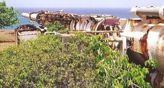 | Project HARP 16 inch Used with permission of Stephen E. Mendes - visit his Barbados Photo Gallery Credit: © Stephen E. Mendes |
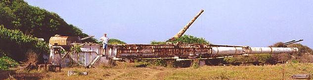 | Project HARP 16 inch Used with permission of Stephen E. Mendes - visit his Barbados Photo Gallery Credit: © Stephen E. Mendes |
1965 March - . LV Family: Martlet. Launch Vehicle: Martlet 4.
- Martlet 4 orbital gun-launched rocket design. - .
Nation: Canada.
It was not until 1964, when agreements between the Canadian and the US governments permitted stable funding over the following three years, that HARP was able to seriously consider an orbital program. The Martlet 4 program began in the spring of 1965 with extensive parametric studies which showed that meaningful payloads could be launched into low Earth orbit from the 16 inch L86 HARP gun on the Barbados flight range using a full bore, 3 stage rocket vehicle.
1966 September - . LV Family: Martlet. Launch Vehicle: Martlet 4.
- Martlet 4A orbital gun-launched rocket tests. - .
Nation: Canada.
Development trials for the Martlet 4A began in the fall of 1966 with tests proceeding into early 1967. The majority of the early work was conducted on the Highwater, Quebec test range where the structural integrity of the Martlet 4A motor during gun-launching was proven. Prior to the abrupt end of the HARP project in July 1967, soft recovery trials and flight testing had been planned for the winter of 1967/1968. At nearly one ton the Martlet 4A holds the worlds record for being the largest rocket motor ever fired from a gun.
Back to top of page
Home - Search - Browse - Alphabetic Index: 0- 1- 2- 3- 4- 5- 6- 7- 8- 9
A- B- C- D- E- F- G- H- I- J- K- L- M- N- O- P- Q- R- S- T- U- V- W- X- Y- Z
© 1997-2019 Mark Wade - Contact
© / Conditions for Use