
Home - Search - Browse - Alphabetic Index: 0- 1- 2- 3- 4- 5- 6- 7- 8- 9
A- B- C- D- E- F- G- H- I- J- K- L- M- N- O- P- Q- R- S- T- U- V- W- X- Y- Z
Dynasoar
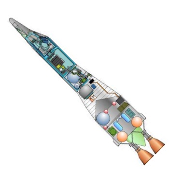
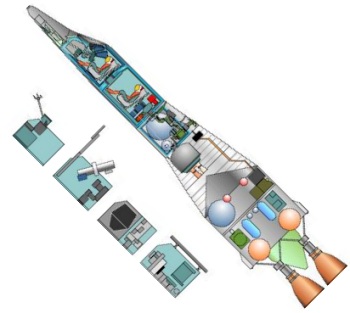
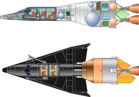
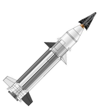
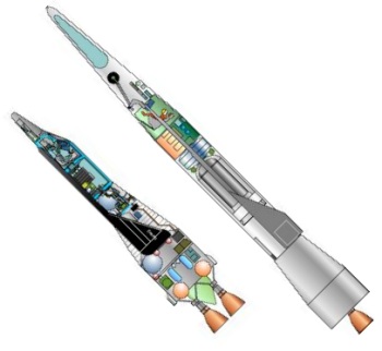 Robo vs Dynasoar Robo and Dynasoar cutaway views, to scale. Robo, from fore to aft: coolant tanks for active structure cooling during re-entry; landing gear; avionics bay; cockpit for single crew; equipment pay; propellant tank bay; nuclear weapon (ejected through rear); transtage for maneuvering in space. Dynasoar: nose skid; cabin for single crew; conditioned payload bay for experiments, weapons, or additional crew; equipment/transition section with cooling equipment, large hydrogen tank for electrical power generator; transtage for maneuver in orbit. |
AKA: X-20A. Status: Cancelled 1963. Payload: 450 kg (990 lb). Thrust: 71.19 kN (16,004 lbf). Gross mass: 10,125 kg (22,321 lb). Unfuelled mass: 7,435 kg (16,391 lb). Height: 14.50 m (47.50 ft). Span: 6.34 m (20.80 ft).
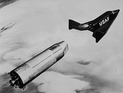
Cancellation in December 1963 came only eight months before drop tests from a B-52 and a first manned flight in 1966.
DynaSoar evolved from the German Saenger-Bredt Silverbird intercontinental skip-glide rocket bomber. Walter Dornberger, former head of Peenemuende, was at Bell Aircraft in the 1950's and developed the Sanger-Bredt concept through various iterations (Bomi and Robo). In typical Pentagon fashion the final development contract went instead to Boeing. Politics resulted in its primary purpose changing during its life (manned space bomber, high speed test vehicle, reconnaissance platform), with the launch vehicles at various times including Titan I, Titan II, and finally Titan IIIC. Cancellation in December 1963 came only eight months before drop tests from a B-52 and a first manned flight in 1966.
The Dyna-Soar itself would have been developed into Dyna-Soar II, III, X-20X, and Dyna-MOWS (Manned Orbital Weapons System) versions which would have run the gamut of missions - orbital supply, satellite rendezvous and inspection, reconnaissance, research, and orbital bombing.
After its cancellation, the Air Force pursued further development of manned spaceplanes through the Prime, Asset, X-23, and X-24 programs, with suborbital launch of subscale lifting body designs. B-52 drop tests of the X-24A and X-24B lifting body designs continued into the mid-1970's. Reportedly there were also black programs leading to suborbital flight and re-entry of a full-size unmanned lifting body patterned after the NASA HL-10. In the end, the Air Force was pressured by the Nixon Administration to accept participation in the space shuttle program in lieu of separate development of their own designs.
The klaxon sounds in the hardened silo deep beneath the earth. A space-suited astronauts run from the ready room, grabs the bar over the hatch, and hoists his legs into the cockpit. The ground crew attach his suit hoses, check that he is strapped into the ejection seat. The pilot closes the hatch above him. The blast doors open, the rocket is raised to the surface of the earth. Minutes later the Titan roars from the silo, launching the Dyna-Soar space bomber on an intercontinental nuclear strike mission.
This was the original vision of Dyna-Soar, the penultimate manned space bomber project of the 1950's. Following evaluation of the Robo space bomber proposals in the summer of 1957, the decision was made to combine several parallel Air Force and NACA manned spaceplane projects into a single effort. These included the SR 126 Robo; the System 459L Brass Bell hypersonic reconnaissance vehicle; and the System 610A Hywards follow-on to the X-15. The secret form DD-613 was completed on 23 August 1957 for System 464L with the confidential description 'Hypersonic Glide Rocket Weapon System', the confidential nickname 'Dyna-Soar' (for Dynamic Soarer), and the unclassified title 'Hypersonic Strategic Weapon System'.
The proposed project would develop a manned, winged vehicle that would be rocket-boosted to hypersonic speed at an altitude above 30 km. It would then glide from 10,200 to 40,800 km, depending on the mission. The project was to be completed in three phases:
- Dyna-Soar I would be a hypersonic research vehicle, boosted to 100 km altitude and 5.5 km/sec in its first version. This velocity would be increased later in the test program by the addition of a second stage. Range on test flights would be between 1800 and 5500 km. The booster could be powered by two of the high-performance liquid fluorine/hydrazine Chariot motors being developed by Bell. If these were not available in time, alternates would be a single Atlas sustainer engine or the X-15 XLR-99. Air-drop flights of the Dyna-Soar I were expected in March 1963, followed by single-stage booster flights a year later, and two-stage near-orbital booster flights by the end of 1965. This phase would replace the Hywards project and be accomplished in collaboration with NACA.
- Dyna-Soar II would be a manned hypersonic reconnaissance vehicle, in replacement of the Brass Bell. This would use production versions of the Phase I hardware to boost the glider to 52 km altitude and 5.5 km/sec. From there it would glide at hypersonic speed over a range of 10,200 km. The pilot would monitor the operation of automated reconnaissance systems, which would consist of a high resolution camera, a side-looking radar, and 'ferret' (ELINT) sensors. Operation of these sensors at high speeds and under conditions of high airframe heating were considered to be a major development issue. The booster was expected to be powered by an Atlas sustainer engine, although use of the Chariot booster was a possibility if it could be developed in time. Dyna-Soar II would begin drop tests in January 1966, followed by boosted tests by the end of 1967. An operational weapons system was to be deployed in mid-1969. This would allow it to replace A-12 reconnaissance planes expected to be vulnerable by that time. If needed, Dyna-Soar II could be equipped with an interim nuclear weapons delivery capability if advances in Soviet development of anti-ballistic missile systems warranted that.
- Dyna-Soar III would be a full-fledged manned, hypersonic, global, strategic bombardment and reconnaissance system. It would fulfill the Robo requirement, and require a multi-stage launch vehicle to take it to near-orbital velocity (7.6 km/sec) at 90 km altitude. Temperature loads were expected to be no greater than that for Dyna-Soar II, but the cooling system would be required to operate for a much longer period. A significant technical problem was expected to be achieving he desired 900 m CEP weapons delivery accuracy. First glide flight was expected in January 1970, followed by the first all-up boosted spaceflight in mid-1971. The Dyna-Soar III global weapon system would become operational in mid-1974.
The Dyna-Soar could attack enemy targets from any direction. At its low approach altitude enemy radar systems would only provide three minutes warning of the attack, as opposed to twenty minutes for an ICBM. Unlike a ballistic missile, it could be recalled or retargeted during the mission. On the reconnaissance mission, it could glide over enemy targets between 45 and 90 km altitude, providing better resolution than orbiting satellites at much higher altitudes. The data would be available for analysis within hours of the overflight, compared to having to wait for days for recovery of the capsules from spy satellites. The enemy would also have no warning to conceal its activities, unlike a satellite in its predictable orbit.
The Air Force considered 12 contractors as capable of bidding on the program. Nine vendor teams submitted bids by March 1958. These were broken into two groups: vehicles which would be accelerated to orbital velocity at 120 km altitude and achieve global range by actually being in orbit; and sub-orbital vehicles that would reach near-orbital speed at 90 km altitude and glide around the planet. The proposals may be summarized as follows:
Satelloid Proposals
- Republic: Delta wing glider, 7,300 kg mass. Three solid propellant stage booster. Separate 'space-to-earth' 2930 kg missile. Global range.
- Lockheed: Delta wing glider, 2,300 kg mass. Modified Atlas ICBM booster. Sub-global range. Booster judged to be insufficient to achieve either satelloid velocity or global range.
- North American: X-15B glider, 6,800 kg mass. Two-place X-15B, boosted by a unique one-and-a-half stage booster with expendable drop tanks for the X-15B. Global range.
- Douglas: Arrow-wing glider, 5,900 kg mass. 3 x Minuteman solid stage booster. Suborbital velocity in Phase I using three modified Minuteman stages in parallel. Addition of another stage would give the vehicle orbital capability, although the planned life support system was not designed for sustained flight.
- McDonnell: Arrow-wing booster, 5,500 kg mass. Modified Atlas ICBM booster. Suborbital velocity in Phase I.
- Convair: Delta wing booster, 5,100 kg mass. Hypersonic aircraft using air-breathing engines. No booster was proposed. Suborbital velocity in Phase I.
- Martin+Bell: Delta wing glider, 6,050 kg mass. Titan ICBM booster. Two crew. Capable of orbital velocity in Phase I. Actively cooled airframe.
- Boeing+Vought: Arrow-wing glider, 2,950 kg mass. Minuteman stages used as booster. Payload only 230 kg including one crew. Capable of orbital velocity in Phase I. Passively cooled airframe using refractory metals.
- Northrop: Delta wing glider, 6,450 kg mass. Hybrid booster - solid fuel burned using a liquid oxidizer, plus an all-liquid core. Suborbital velocity in Phase I.
During the study period, something extraordinary happened: Boeing's configuration evolved from its original Buck Rogers concept, festooned with fins, to something nearly identical to Bell's glider. Boeing's March 1958 configuration was essentially a tetrahedron; triangular planform with a diamond cross-section. That shape was driven by the desire to eliminate thermal stresses by using a determinate truss primary structure. But Boeing already recognized that the ventral fins were thermally untenable and would have to go. They were driven to a flat-bottomed configuration with distinct wings to reduce heating and improve landability. By the time of the final proposals in June 1959, the competing glider systems were nearly indistinguishable, except that Bell's glider used a more sophisticated double-delta wing, foreshadowing the space shuttle of 15 years later. In a shock move, Boeing was selected for the glider in June 1959.
This was Bell's swan song. The small but innovative company had invested millions of its own money in the Bomi and Dyna-Soar. But Bell was considered more of a prototype house by the Air Force. In World War II they were relegated to production of fighters to be sent to the Soviet Union on lend-lease. Although they had built the first American jet aircraft and the X-1, the first aircraft to break the sound barrier, they had not won a full-scale development contract for a manned aircraft since 1955. Boeing, on the other hand, was the premier builder of SAC's B-52 bombers and Minuteman ICBM's. To compensate it for the loss of the B-70 competition at the end of 1957, it was perhaps considered logical for it to build the successor.
On the other hand the service greatly preferred Martin's booster proposal (Titan I for the suborbital tests, Titan C for global flights). Boeing's vague proposal was to use Atlas-Centaur for suborbital flights, and a booster 'to be determined' for orbital flights. The contract awards for Dyna-Soar, were announced on November 9, 1959. By then the program was had gone down to two phases, and then back to three phases - a suborbital test Phase 1, an orbital test Phase 2, and an operational weapon system in Phase 3.
The selection of the Titan C for the Phase 2 booster was controversial. This was a Titan II booster stage topped by a new liquid oxygen/hydrogen upper stage. Even though Aerojet already had the engine under test in Sacramento, the Eisenhower administration wasn't interested in developing yet another new orbital launch vehicle. There were also elements in the Air Force pushing their Space Launching System family of modular launch vehicles. And there was an Air Force requirement, beyond Dyna-Soar, for development of a large booster for its SLV-4 requirement. This new vehicle would be needed by the late 1960's for launch of ten-metric ton reconnaissance satellites into low orbit and heavy communications, ELINT, and early warning satellites into high orbits. Production of Titan I boosters for Phase 1 was authorized while a decision on the orbital booster was deferred.
The first development contract was not issued until April 1960. While glider development continued at Boeing, the booster kept changing. By January 1961 it was decided to use the Titan 2 instead of the Titan 1 for the suborbital flights. In July 1961 the Air Force recommended production of its visionary Space Launching System for the SLV-4 requirement. The A-388 'Phoenix' variant of the modular booster would provide Dyna-Soar's ride to orbit. This was overturned three months later and the Titan 3 became the heavy-launch vehicle for the USAF. A month later, at the end of 1961, it was decided to dump the Titan 2 sub-orbital phase of Dyna-Soar launches, and use the Titan 3 alone for Dyna-Soar launches.
Meanwhile development of the glider was proceeding well. By the end of 1962 critical design reviews of all major subsystems had been completed. Major breakthroughs had been achieved in high temperature materials and fabrication of parts for the airframe was underway. Delivery of the first Dyna-Soar was to be made by October 1964 and first orbital launch by the end of 1965. While the first glider test would be 14 months later than the original July 1957 schedule, the first orbital flight was expected six months earlier.
Dyna-Soar was seemingly doomed from birth over controversy over its mission and the lack of a strong sponsor. The Eisenhower administration wanted to limit it to suborbital missions (so as not to infringe on the new NASA agency's mission of manned orbital flight). Once Eisenhower was replaced by Kennedy, the catastrophic new Secretary of Defense, Robert McNamara, began to work his malignant magic. There was no weapons system immediately resulting from Dyna-Soar. Nor did he believe there was any need for the military to waste so much money on an aeronautical research vehicle. The back-and-forth was extremely tedious and can be traced through the chronology below. Suffice to say after reviews, audits, and special studies ad nauseum the project was killed by McNamara in December 1963.
It was replaced by the Manned Orbiting Laboratory (MOL), equipped with a Gemini capsule, also launched by a Titan 3 booster. McNamara killed a project in being, with drawing release nearly 100% complete, and the first spacecraft one month away from final assembly. Expenditures were under control and Boeing had already spent $ 253.5 million of its $ 530 million development budget. Captive-carry flights would have begun within the year. In its place was a vague concept not even studied in any detail yet. After six years of development, it would in turn be cancelled in 1969 after wasting $ 1.5 billion. It was a typical example of McNamara's criminally poor judgment.
If Dyna-Soar and the Space Launching System had been completed, the United States would have had by 1965 a modern modular launch vehicle launching a reusable manned spaceplane -- something it now hopes to accomplish with the Delta IV / OSP by 2010. The nation could have been spared the false premise of the shuttle program and had a space station ferry in being by the beginning of the 1970's. It might even have been flying well into the 21st Century, while the Gemini, Apollo, and Shuttle were consigned to the trash heaps of history.
Technical Description of the Dyna-Soar
Configuration
The glider had a 72.48 deg straight delta wing with a flat bottom. The aft fuselage was ramped, found desirable to provide directional stability at transonic speeds. It was 10.78 m long, with a wingspan of 6.34 m and a wing area of 32 sq m. The design provided a hypersonic lift-to-drag ratio of from 0.8 to 1.9 at hypersonic speeds. This was sufficient to give it a maximum cross-range of 3150 km. This meant if it had to divert from a planned landing at Edwards Air Force base, California, it could land anywhere from Juneau, Alaska, to Talaro, Ecuador, including any airfield in the continental United States. The Dyna-Soar's unique wire-brush skids allowed it to land even on compacted earth runways as short as 2400 m.
The glider had a design mass of 5,055 kg with a 450 kg return payload for the 3150 km cross-range. This design mass was based on the original expected performance of the heat shield materials. Tests prior to cancellation of the project indicated higher-than-expected emissivity of the heat shield. This meant the flight vehicle could have a mass of 6,400 kg with a return payload of 1800 kg at the 3150 km cross range. This capability was to be exploited in planned follow-on versions.
In orbit the glider remained attached to the third stage of the Titan 3. This transtage was a restartable rocket capable of enormous maneuvers. Before ignition it had a gross mass of 12,250 kg, of which 10,300 kg was storable nitrogen tetroxide/Aerozine-50 propellants. The transtage would fire initially to place the Dyna-Soar in orbit. Available remaining propulsion would depend on the mission initial orbit and glider mass. On a typical mission it was expected the total mass (glider+transtage) orbited would be 12,700 kg, leaving the transtage with 5700 kg of propellants, enough for a single maneuver of over 2 km/sec. Such huge maneuvers would greatly complicate the enemy's ability to predict the overflight path and time of the Dyna-Soar on a reconnaissance, bombing, or satellite interception mission.
The Air Force was especially interested in exploring the possibilities of 'synergistic' orbital maneuver. This would involve the X-20 entering the upper atmosphere, and using its aerodynamic maneuverability to change the orbital plane. The transtage would then boost the spacecraft back into orbit. This would change the maximum plane change from 15.8 deg for the pure propulsive engine burn to 20.3 deg for the 'synergistic' turn.
In the fairing between the glider and the transtage was a solid-propellant abort rocket adapted from the Minuteman third stage. This would be used for aborts during launch to blast the glider away from the booster. On orbit, it could be used for emergency retro-fire in case of a transtage propulsion failure.
Structure
The internal structure of the X-20A was a truss structure of Rene 41 steel. This was designed to compensate for thermal expansion of the hot structure during re-entry. Within the body truss were four bays - forward pilot's compartment, a central equipment compartment, aft equipment bay, and secondary equipment bay.
The upper wing, body, and inside fin surfaces were also of Rene 41. Coated molybdenum was used for the leading edge panels and the lower wing surface. The nose cap was of zirconium. Maximum re-entry temperatures during a maximum lateral range re-entry would 2010 deg C at the nose-cap, 1550 deg C on the wing leading edge, and 1340 deg C on the wing lower surface. The internal structure would stabilize at 980 deg C.
Systems
Avionics
The X-20 would not be controllable throughout its speed range with purely manual controls. Therefore a control augmentation system was provided, which could operate in four control modes, all of them fly-by-wire. A side-arm controller provided pitch and roll inputs while yaw commands were via conventional aircraft rudder pedals. The pilot was able to use these controls for manual flight of the Titan 3C launch vehicle during the boost to orbit, if needed. In space, these controls commanded one of two redundant hydrogen peroxide thruster systems for orientation. During re-entry, the control system operated a mix of thruster and aerodynamic controls until the glider reached a dynamic pressure of 0.68 bar. From that point purely aerodynamic controls were used. The thrusters were shut down and the remaining hydrogen peroxide propellant was pumped overboard. Over 8,000 pilot-hours were spent in X-20 simulators before the program was cancelled. These showed the glider's longitudinal and lateral handling characteristics were rated between good and satisfactory in the speed range Mach 1 to Mach 27.
The inertial navigation system was developed by Honeywell at their Saint Petersburg, Florida facility. It used an adaptation of the inertial measurement unit developed for the Bomarc-B missile and later adapted for the Centaur upper stage. The guidance computer was the same used in the Hound Dog missile. The system was tested in-flight in an F-101B fighter and on a high-speed sled at Holloman AFB. After the X-20 cancellation, the system was tested at extreme speed and altitude in the X-15.
For the re-entry the pilot was provided with a unique 'energy management display' which consisted of a series of transparent overlays on a cathode-ray tube. The system was driven by the guidance computer, which changed the overlays every 300 m/s as the re-entry progressed. Two dots were projected on the cathode-ray tube. One showed the current angle of attack and bank angle of the glider; the other the angles the pilot would have to fly to reach the selected airfield. The overlay included a line indicating air vehicle structural limits to ensure the pilot did not over-maneuver the aircraft. The guidance system could store a maximum of ten airfield locations.
Systems
The internal compartments of the Dyna-Soar were encased in 'water walls' which provided passive cooling. These reduced the 980 deg C re-entry equilibrium temperature of the airframe truss structure to 90 deg C and allowed the pressure shells of the compartments to be of conventional aluminum. Cooling systems in the compartments further reduced the maximum internal temperature to 46 deg C. The pilot compartment was pressurized to 0.5 atmosphere, equivalent to an altitude of 5500 m, but with a mixture of 43.5% oxygen and 56.5% nitrogen. The payload compartment was pressurized at 0.7 atmosphere with 100% nitrogen. The other two bays were not pressurized, but had nitrogen purging systems in the case of fires.
The pilot's compartment housed the inertial guidance system, the flight control system electronics, pilot displays, controls, ejection seat, and gas supplies for windshield cover jettison and landing gear extension. The pilot had a view at all times through two side windows. The three-piece forward windshield was covered by a heat shield during ascent, orbital operations, and re-entry. It was only blown off when the glider had slowed below Mach 6, for use on landing. However tests by Neil Armstrong with a modified F5D Stingray fighter showed landing could be safely made using only the side windows if this failed to jettison. The ejection seat could only be used at subsonic speeds between 1,000 and 130 kph.
The equipment compartment provided just over two cubic meters of volume, to be occupied during flight tests with the 450 kg of the Test Instrumentation Subsystem. This processed and recorded data from 750 sensors that captured glider temperature, pressure, loads, subsystems performance, pilot biometrics, and heat flux.
The aft equipment bay was a narrow compartment containing the liquid nitrogen supply, the hydrogen peroxide propellant tanks, and some power system controls.
The large secondary power bay was dominated by the huge liquid hydrogen tank. This worked with two redundant liquid oxygen tanks to provide propellant for the unique Auxiliary Power Unit that provided 12 kVA 400 cycle AC power for the Dyna-Soar. It also housed the glycol secondary cooling system.
Mission Profile
For the 'single-orbit' test flights, Dyna-Soar would be boosted from Cape Canaveral by the Titan 3C and transtage to 7.53 km/s at 98 km altitude. It would then coast to an apogee of 146 km over South Africa. The transtage would be jettisoned over the Indian Ocean, and the long re-entry glide would continue from there until landing at Edwards Air Force Base, California. For multi-orbit flights, booster cut-off would be only 20 m/s faster and 600 m higher. But then the glider would coast to 183 km altitude, where the transtage would fire to circularize the orbit. After three circuits of the earth, the transtage would fire again over Angola to brake out of orbit, with the return demonstrating the spacecraft's cross range capability and the landing again at Edwards.
Growth Versions
Heavier and more capable versions of the Dyna-Soar were planned to follow on the basic ten-flight program. These could use both refurbished gliders from the basic program and new-build spacecraft. The basic vehicle had the capability for a 450 kg return payload and 300 m/s delta-v capability. Expected improvements were as follows:
- Increase to 1,000 m/s delta v capability through improved Titan 3C performance
- Increase to 900 kg return payload through glider weight reduction program
- Increase to 1700 m/s delta v through introduction of an improved abort rocket and transition section modifications for multi-orbit flight
- Increase to a maximum return payload of 1800 kg through improved emissivity of the heat shield. This would correspondingly lower the maximum delta v for the transtage to 1.2 km/s
- Use of synergistic maneuver for plane change to reach an equivalent delta v of 2.0 km/s
Following the funded ten-flight test series, the Dyna-Soar could be used in a number of roles. While the space bomber mission was no longer discussed by late 1963, it would be a useful platform for other Air Force missions. The basic X-20A could be modified to accommodate the following payloads:
- Addition of a two pilot positions in the equipment bay for rescue or extra-vehicular tests
- Installation of alternate packages (high resolution camera/infrared, high resolution side-looking radar, or ELINT) for military reconnaissance missions.
- Technology or scientific research payloads, which could be operated or repaired by the pilot if needed
- Rendezvous and/or satellite retrieval packages for the SAINT II enemy satellite inspection and nullification mission
Longer-term, the X-20X was a follow-on version for space station ferry missions. The interior of the glider was substantially rearranged to provide for four passenger seats behind the pilot. The aft equipment bay was eliminated and all equipment was moved to the secondary power bay. The abort motor was eliminated. That and the performance improvements listed resulted in substantial space and mass margins for large payloads in a bay in the transition section between the glider and transtage. Grappling arms provided for docking of the entire upper fuselage with a space station.
The X-20 was pushed as an alternate to the Gemini as a space station ferry vehicle in the twilight days of the program. If only it had been accepted, the US would have had a space station and winged ferry vehicle flying before the end of the 1960's.
Crew Size: 1. Habitable Volume: 3.50 m3. Spacecraft delta v: 900 m/s (2,950 ft/sec).
| Brass Bell American manned combat spacecraft. Study 1956. Hypersonic manned reconnaissance spaceplane project of the 1950's. Predecessor to Dynasoar. |
| Hywards American manned combat spacecraft. Study 1956. Hypersonic manned test spaceplane project of the 1950's. Predecessor to Dynasoar. |
| M1 Manufacturer's designation for [Mars M1] mars orbiter. |
| M2b Version of M2 lifting body proposed in 1958 as an alternate to the Dynasoar winged glider configuration. |
| SAINT II American manned combat spacecraft. Cancelled 1961. At the beginning of the 1960's, the USAF examined a number of approaches to a manned spacecraft designed to rendezvous with, inspect, and then, if necessary, destroy enemy satellites. |
| Asset American manned spaceplane. 6 launches, 1963.09.18 (ASSET 1) to 1965.02.23 (ASSET 6). One part of the Dynasoar manned spaceplane project was ASSET ( 'Aerothermodynamic Elastic Structural Systems Environmental Tests') . |
| Dynasoar 3 Planned Dynasoar first manned single-orbit flight. The flight would have been devoted to demonstrating pilot control of the spacecraft and evaluation of the systems (this was to have followed two unmanned flight tests). Project cancelled December 1963. |
| Dynasoar 4 Planned second manned Dynasoar single-orbit flight. Objectives were to demonstrate maneuver in orbit and during re-entry, and systems evaluation. Project cancelled in December 1963 |
| Dynasoar 5 Planned third manned Dynasoar single-orbit flight; would demonstrate maneuver in orbit and during re-entry, and systems evaluation. Project cancelled in December 1963. |
| Dynasoar 6 Planned fourth manned Dynasoar single-orbit flight; would demonstrate maneuver in orbit and during re-entry, and systems evaluation. Project cancelled in December 1963. |
| Dynasoar 7 Planned fifth manned Dynasoar single-orbit flight. Would demonstrate reuse of a minimally-refurbished spacecraft flown on an earlier mission. Project cancelled in December 1963 |
| Dynasoar 8 Planned sixth manned Dynasoar single-orbit flight. Would demonstrate maneuver in orbit and during re-entry, and a precision recovery. Project cancelled in December 1963 |
| Dynasoar 9 Planned first multi-orbit flight and seventh manned flight of Dynasoar would have the objectives to demonstrate maneuver in orbit and during re-entry, and a precision recovery. Project cancelled in December 1963 |
| Dynasoar 10 Planned eighth manned flight, second multi-orbit flight, and final flight of the Dynasoar program would have the objectives to demonstrate maneuver in orbit and during re-entry, and a precision recovery. Project cancelled in December 1963 |
Family: Spaceplane, US Rocketplanes. People: Saenger. Country: USA. Spacecraft: Dynasoar Glider, Dynasoar AS. Launch Vehicles: Titan I, Titan II, Titan IIIC, Astro IV, Soltan, Titan C, RBSS, Saturn I. Stages: Titan Transtage. Agency: Boeing. Bibliography: 148, 152, 158, 17, 18, 26, 36, 4288, 44, 47, 48, 483, 583.
 | Dyna Soar Credit: USAF |
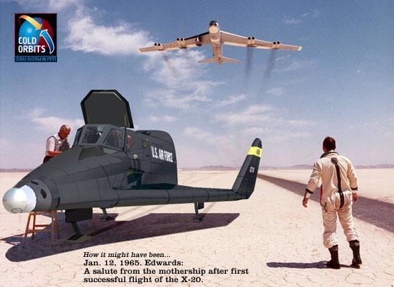 | B-52 overflies X-20 B-52 overflies Dynasoar after first drop test. Credit: © Dan Roam |
 | X-20A Credit: © Mark Wade |
 | X-20A Credit: © Mark Wade |
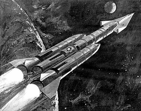
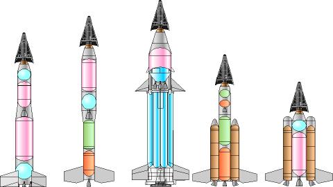
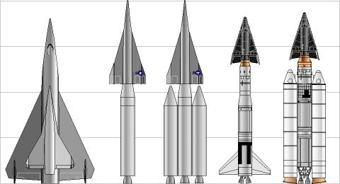 | Boost-Glide Vehicles US Boost-glide vehicles of the 1950's: From left, Bomi, Robo single and parallel booster versions, Boeing Dynasoar with Titan 1 and Titan 2 boosters |
 | X-20A Credit: © Mark Wade |
 | X-20A Variants Credit: © Mark Wade |
 | X-20X Credit: © Mark Wade |
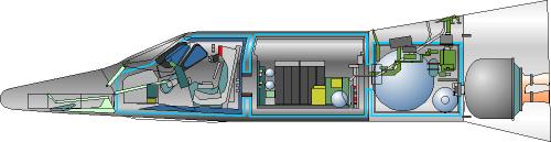
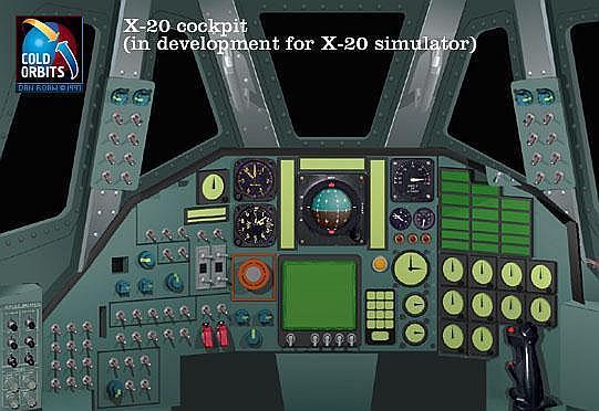 | X-20 cockpit View of the X-20 cockpit. In addition to single crew member, payload bay behind cockpit could have accepted additional crew member or 450 kg military/scientific payload. Credit: © Dan Roam |
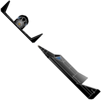
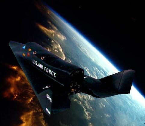
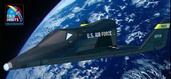 | X-20 Dynasoar X-20 Dynasoar in re-entry configuration Credit: © Dan Roam |
 | Dynasoar |
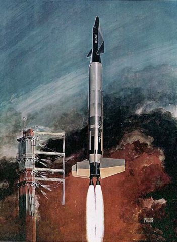
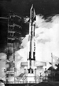 | X-20A / Titan 1 Credit: USAF |
 | X-20 / Titan 1 Credit: Lockheed-Martin |
 | X-20/Saturn I Credit: © Mark Wade |
 | X-20 Early Concept Credit: Aerojet |
 | X-20 Launch Vehicles SLV-4 / X-20 Launch Vehicles - from left, Titan I, Titan C, Saturn I, Titan 3, Phoneix (SLS A-388) Credit: © Mark Wade |
 | X-20 Dynasoar X-20 Dynasoar at sunrise Credit: © Mark Wade |
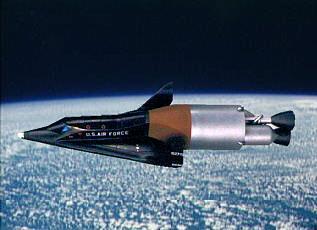 | X-20 Dynasoar X-20 Dynasoar in orbit Credit: © Mark Wade |
 | Titan 3 LV with X-20 The original mission of the Titan 3 booster was to launch the X-20 Dynasoar manned spaceplane into orbit. Credit: © Mark Wade |
 | X-20 3 View Credit: © Mark Wade |
1933 December 15 - . LV Family: German Rocketplanes. Launch Vehicle: Saenger Antipodal Bomber.
- Rakatenflugtechnik published. - . Nation: Germany. Spacecraft: Dynasoar. Eugen Sänger of Germany published his classic Rakatenflugtechnic, which dealt with rocket motor design and high-speed flight in the atmosphere..
August 1944 - . LV Family: German Rocketplanes. Launch Vehicle: Saenger Antipodal Bomber.
- Saenger antipodal bomber - .
Nation: Germany.
Related Persons: Saenger.
Spacecraft: Dynasoar.
Eugen Saenger and Irene Bredt issue their final 400-page report on the Saenger antipodal bomber - a rocket boosted skip-glide spaceplane with global range. Only 100 numbered copies are printed, and distributed to German political and scientific leaders. The futuristic scheme would have taken many years to develop and was of only academic interest to the German government. But copies of the report fell into the hands of the Americans and Russians after the war, spawning major development projects in the fifties.
1946 May 1 - .
- RAND study of a capsule with wings for manned space flight. - . Nation: USA. Spacecraft: Dynasoar. RAND authorities determined that it was feasible to design a capsule with wings for manned space flight..
1952 April 17 - .
- Bell proposal for Bomi. - . Nation: USA. Spacecraft: Bomi, Dynasoar. The Bell Aircraft Company offered a proposal to the Wright Air Development Center for a manned bomber-missile, known as Bomi..
1954 April 1 - .
- Bell contract for an advanced, bomber-reconnaissance weapon system. - . Nation: USA. Spacecraft: Bomi, Dynasoar. The Air Force and the Bell Aircraft Company arranged a contract for the study of an advanced, bomber-reconnaissance weapon system..
1955 January 4 - .
- ARDC headquarters issued System Requirement 12. - . Nation: USA. Spacecraft: Bomi, Dynasoar. ARDC headquarters issued System Requirement 12, which called for studies of a reconnaissance aircraft or missile possessing a range of 3,000 nautical miles and capable of reaching 100,000 feet..
1955 May 12 - .
- Piloted, high-altitude, weapon system by 1959. - . Nation: USA. Spacecraft: Bomi, Dynasoar. General Operational Requirement 12 for a piloted, high-altitude, reconnaissance weapon system available by 1959..
1955 September 21 - .
- Bomi contract extended as Special Reconnaissance System 118P. - . Nation: USA. Spacecraft: Bomi, Dynasoar. The Bomi contract of the Bell Aircraft Company was extended as a study for the Special Reconnaissance System 118P..
1955 December 19 - .
- Manned hypersonic rocket-powered weapon system. - .
Nation: USA.
Spacecraft: Bomi,
Dynasoar.
US industry to investigate the feasibility of a manned, hypersonic, rocket-powered, bombardment and reconnaissance weapon system. The Air Force requested the aviation industry to investigate the feasibility of developing a manned, hypersonic, rocket-powered, bombardment and reconnaissance weapon system.
1956 March 1 - .
- Hywards development plan. - . Nation: USA. Spacecraft: Bomi, Dynasoar, Hywards. The Research and Target Systems Division of ARDC headquarters completed an abbreviated development plan for a glide-rocket, research system, designated Hywards. .
1956 March 20 - .
- Brass Bell. - . Nation: USA. Spacecraft: Bomi, Brass Bell, Dynasoar. The Air Force and Bell Aircraft Company completed negotiations for a study contract involving Reconnaissance System 459L, Brass Bell..
1956 June 12 - .
- System Requirement 126 for Robo rocket-bomber. - . Nation: USA. Spacecraft: Bomi, Dynasoar, Robo. ARDC headquarters issued System Requirement 126, outlining the requirements for a rocket-bomber, named Robo..
1956 October 1 - .
- X-15 follow-on work begun. - . Nation: USA. Class: Manned. Type: Manned spaceplane. Spacecraft: Dynasoar. NACA scientists initiated examination of the need for a follow-on manned-rocket research vehicle to the X-15, following ARDC inquiries concerning a boost-glide vehicle..
1956 October - .
- Follow-on to the X-15. - . Nation: USA. Spacecraft: Dynasoar. NACA scientists were engaged in preliminary studies of the need for a follow-on, manned-rocket research vehicle to the X-15..
1956 November 6 - .
- Hywards abbreviated development plan. - . Nation: USA. Spacecraft: Dynasoar, Hywards. ARDC headquarters issued System Requirement 121, requesting information from Air Force agencies for the preparation of a Hywards abbreviated development plan..
1956 November - .
- Follow-on to the X-15 project discussed. - .
Nation: USA.
Spacecraft: Dynasoar.
Personnel of the Air Research and Development Command approached NACA officials on the possible cooperation of NACA in a research airplane project as a follow-on to the X-15 project. NACA agreed to consider the plan and directed its laboratories to initiate feasibility studies relative to the range of speed for the proposed vehicle and an estimate of the time frame in which the vehicle could be developed.
1957 February 14 - .
- X-15 follow-on studied. - .
Nation: USA.
Class: Manned.
Type: Manned spaceplane. Spacecraft: Dynasoar.
NACA established "Round Three" Steering Committee to study feasiblity of a hypersonic boost-glide research airplane. "Round Three" was considered as the third major flight research program which started with the X-series of rocket-propelled supersonic research airplanes, and which considered the X-15 research airplane as the second major program. The boost-glide program eventually became known as DynaSoar.
1957 April 30 - .
- Development plan encompassing all hypersonic weapon systems. - . Nation: USA. Spacecraft: Bomi, Brass Bell, Dynasoar, Hywards, Robo. Air Force headquarters directed the Air Research and Development Command to formulate a development plan encompassing all hypersonic weapon systems..
1957 June 20 - .
- Two NACA groups focused their efforts on the problems involved in manned space flight. - . Nation: USA. Spacecraft: Dynasoar. One group concerned themselves with performance of aircraft at high speeds and altitudes and with rocket research; the other group, with problems associated with hypersonic flight and reentry..
1957 June 20 - .
- Robo evaluation committee. - . Nation: USA. Spacecraft: Dynasoar, Robo. A committee, with representation from ARDC headquarters, the Wright Air Development Center, the Cambridge Air Force Research Center, and the Air Materiel Command, was formed to evaluate contractor studies on Robo..
1957 October 10 - .
- Hywards, Brass Bell, and Robo consolidated into Dyna-Soar. - .
Nation: USA.
Spacecraft: Bomi,
Brass Bell,
Dynasoar,
Hywards,
Robo.
The launch of Sputnik spurs immediate actions within the government to accelerate manned spacecraft work. ARDC headquarters consolidated Hywards, Brass Bell, and Robo studies into a three-step abbreviated development plan for System 464L, Dyna-Soar. On the same day a NACA Hypersonic Steering Committee met to consider the best configuration for such a vehicle. Langley's Faget pushed non-gliding ballistic capsules, another NACA group felt lifting bodies were the best solution, but the majority of participants favoured the flat-bottomed glider configuration.
1957 October 14 - .
- Dynasoar selected as X-15 follow-on. - . Nation: USA. Class: Manned. Type: Manned spaceplane. Spacecraft: Dynasoar. USAF and NACA reviewed preliminary studies dating from 1954 on a boost-glide research vehicle to follow the X-15; all studies were combined into a single plan which was accepted by the Air Force and later designated as Dyna-Soar..
1957 October 15-21 - .
- X-20 Dyna Soar conference. - .
Nation: USA.
Spacecraft: Dynasoar.
A 'Round 3' conference involving studies for a follow-on to the X-15 program, which subsequently led to the X-20 Dyna Soar, was held at the Ames Aeronautical Laboratory. During the course of the meeting, Alfred J. Eggers, Jr., of Ames advanced several proposals for possible manned satellite vehicle development projects.
1957 November 15 - .
- Abbreviated development plan for Dyna-Soar. - . Nation: USA. Spacecraft: Dynasoar. Air Force headquarters approved the abbreviated development plan for Dyna-Soar..
1957 November 25 - .
- $3 million of fiscal year 1958 funds for Dyna-Soar. - . Nation: USA. Spacecraft: Dynasoar. Air Force headquarters issued Development Directive 94, which allocated $3 million of fiscal year 1958 funds for Dyna-Soar..
1957 December 21 - .
- Implementation of the Dyna-Soar program. - . Nation: USA. Spacecraft: Dynasoar. ARDC headquarters issued System Development Directive 464L, directing the implementation of the Dyna-Soar program..
1958 January 25 - .
- Dynasoar request for proposal - .
Nation: USA.
Spacecraft: Dynasoar.
After surveying 111 potential bidders, the USAF issued Requests for Proposal to ten companies (Bell, Boeing, Vought, Convair, Douglas, General Electric, Lockheed, Martin, North American, Western Electric). Later McDonnell, Northrop, and Republic were also issued RFP's.
1958 January 31 - .
- Expedited man-in-space projects. - .
Spacecraft: Man-In-Space-Soonest,
Mercury,
Dynasoar,
Project 7969.
Air Force headquarters instructed the Air Research and Development Command to expedite man-in-space projects. Air Force headquarters instructed the Air Research and Development Command, in collaboration with the National Advisory Committee for Aeronautics to " expedite the evaluation of existing or planned projects, appropriate available proposals and other competitive proposals with a view to providing an experimental system capable of an early flight of a manned vehicle making an orbit of the earth." Furthermore, it was asserted that it was "vital to the prestige of the nation that such a feat be accomplished at the earliest technically practicable date--if at all possible before the Russians. " It was therefore important that the evaluation determine whether the objective of a manned space flight could be accomplished more readily under the Dyna Soar program or by means of an orbiting satellite. The minimum time to the first orbital flight and the associated costs were to be determined. The approach to this objective was also to furnish tangible contributions to the over-all Air Force astronautics program. Furthermore, the hazard accompanying such a flight was to be the minimum dictated by sound engineering and experimental flight safety practices. If at all possible, pilot safety was to be secured by furnishing an emergency escape system. (Ltr, Lt Gen D. L. Putt, DCS/D, Hq USAF, to Cmdr, ARDG, 31 Jan 58, subj: Advanced Hypersonic Research Aircraft.)
March 1958 - .
- Dynasoar proposals evaluated - .
Nation: USA.
Spacecraft: Dynasoar.
Teaming agreements between various the 13 bidders invited to participate resulted in nine proposals being submitted . The source selection board was divided. John Becker from NACA rejected any designs that corresponded with Langley's Hywards concept: high L/D ratio (typically hypersonic 2.0, subsonic 5.0) and active water cooling systems. On the other hand the USAF evaluators were not happy with intermediate research vehicles with no potential for development into an operational weapons system - as had been proposed by most bidders. The only proposals for true orbital vehicles were those from Boeing-Vought and Bell-Martin, but only the Boeing-Vought vehicle met Becker's criteria.
1958 March 18-20 - .
- NACA Conference on High-Speed Aerodynamics - .
Nation: USA.
Related Persons: Faget.
Spacecraft: Dynasoar,
Mercury.
An 'NACA Conference on High-Speed Aerodynamics' was held at the Ames Aeronautical Laboratory, Moffett Field, California, to acquaint the military services and industrial contractors interested in aerospace projects with the results of recent research conducted by the NACA laboratories on the subject of space flight. The conference was attended by more than 500 representatives from the NACA, industry, the military services, and other appropriate government agencies. Some 46 technical papers were presented by NACA personnel, and included specific proposals for manned space flight vehicle projects. One of these was presented by Maxime A. Faget. Other papers within the category of manned orbital satellites included: 'Preliminary Studies of Manned Satellites, Wingless Configuration, Lifting Body' by Thomas J. Wong and others; 'Preliminary Studies of Manned Satellites, Winged Configurations' by John V. Becker; 'Preliminary Aerodynamic Data Pertinent to Manned Satellite Reentry Configurations' by Jim A. Penland and William O. Armstrong; and 'Structural Design Considerations for Boost-Glide and Orbital Reentry Vehicles' by William A. Brooks and others.
1958 May 20 - .
- Air Force agreement for NACA participation in the Dyna-Soar program. - . Nation: USA. Spacecraft: Dynasoar. The Air Force and the National Advisory Committee for Aeronautics signed an agreement for NACA participation in the Dyna-Soar program..
1958 May 20 - .
- NACA / Air Force Memorandum of Understanding on the DynaSoar I. - .
Nation: USA.
Spacecraft: DynaSoar.
The National Advisory Committee for Aeronautics (NACA) and the Air Force signed a Memorandum of Understanding concerning the principles in the development and testing of the Air Force's Hypersonic Boost Glide Vehicle (Dyna Soar I). The following principles would apply to the project: (1) The project would be conducted as a joint Air Force-NACA project. (2) Overall technical control of the project would rest with the Air Force, acting with the advice and assistance of NACA. (3) Financing of the design, construction, and Air Force test of the vehicles would be borne by the Air Force. (4) Management of the project would be conducted by an Air Force project office within the Directorate of Systems Management, Headquarters, Air Research and Development Command. NACA would provide liaison representation in the project office and provide the chairman of the technical team responsible for data transmission and research instrumentation. (5) Design and construction of the system would be conducted through a negotiated prime contractor. (6) Flight tests of the vehicle and related equipment would be accomplished by NACA, the USAF, and the prime contractor in a combined test program, under the overall control of a joint NACA-USAF committee chaired by the Air Force.
1958 May 20 - .
- Agreed development and testing program for Dyna-Soar. - . Spacecraft: Dynasoar. The Air Force and the National Advisory Committee for Aeronautics (NACA) agreed to the development and testing program for the Air Force's hypersonic boost-glide vehicle, Dyna-Soar..
1958 May 20 - .
- Dynasoar NACA-USAF MOU. - . Nation: USA. Class: Manned. Type: Manned spaceplane. Spacecraft: Dynasoar. NACA-USAF Memorandum of Understanding signed, "Principles for Participation of NACA in Development and Testing of the Air Force System 464L Hypersonic Boost Glide Vehicle (Dyna-Soar I).".
1958 June 16 - .
- Phase I development contracts for Dyna-Soar. - . Spacecraft: Dynasoar. The Air Force awarded Phase I development contracts for the Dyna-Soar boost-glide orbital spacecraft to the Martin Company and Boeing Airplane Company..
1958 June 16 - . LV Family: Titan. Launch Vehicle: Titan C.
- Dynasoar Phase I contracts announced. - .
Nation: USA.
Class: Manned.
Type: Manned spaceplane. Spacecraft: Dynasoar.
Phase I contracts for the Dyna-Soar boost-glide orbital spacecraft are awarded by the USAF to two teams of contractors: one headed by Boeing (Aerojet, General Electric, Ramo-Wooldridge, North American, and Chance Vought), and one headed by Martin (Bell, American Machine & Foundry, Bendix, Goodyear, and Minneapolis-Honeywell). Under the $ 9 million one-year contracts each team was to refine its design, leading to a competitive down-select.
1958 September 30 - .
- $ 10 million procurement fund for fiscal year 1959 canceled from the Dyna-Soar program. - . Nation: USA. Spacecraft: Dynasoar. Air Force headquarters informed Detachment One of ARDC headquarters that the $ 10 million procurement fund for fiscal year 1959 had been canceled from the Dyna-Soar program..
1958 November 1 - .
- The Dyna-Soar preliminary two-step development plan. - . Nation: USA. Spacecraft: Dynasoar. The Dyna-Soar project office completed a preliminary development plan, involving a two-step program: the development of a research vehicle and then a weapon system..
1959 January 7 - .
- $10 million of fiscal year 1959 funds for the Dyna-Soar program. - . Nation: USA. Spacecraft: Dynasoar. Deputy Secretary of Defense, D. A. Quarles reinstated the $10 million of fiscal year 1959 funds for the Dyna-Soar program..
1959 February 17 - .
- General Operational Requirement 12 for an orbital a bombardment system. - . Nation: USA. Spacecraft: Dynasoar. Air Force headquarters revised General Operational Requirement 12. Instead of a high-altitude reconnaissance system, ARDC was to develop a bombardment system..
1959 April 13 - .
- Primary objective of the Dyna-Soar program to be the suborbital exploration of hypersonic flight. - .
Nation: USA.
Spacecraft: Dynasoar.
Dr. H. F. York, the Director of Defense for Research and Engineering, established the primary objective of the Dyna-Soar program as the suborbital exploration of hypersonic flight. This was the first of many disruptions to the program occurred. He declared that Dynasoar should be only a suborbital research vehicle with a maximum velocity of 6.7 km/s, boosted by an existing ICBM. Any military applications were of only secondary importance.
1959 May 7 - .
- USAF System Requirement 201 (Dyna-Soar) - .
Nation: USA.
Spacecraft: Dynasoar.
ARDC headquarters issued System Requirement 201, declaring the purpose of the Dyna-Soar vehicle was to determine the military potential of a boost-glide weapon system and provide research data on flight characteristics up to and including global flight. The Air Force disagreed with the position of the Secretary of Defence's office that Dynasoar be limited to suborbital research flights.
1959 June 1 - . LV Family: Titan. Launch Vehicle: Titan C.
- Dyna-Soar contractors Boeing and Martin selected. - .
Nation: USA.
Spacecraft: Dynasoar.
The Dyna-Soar source selection board completed its evaluation of the proposals of the Boeing Airplane Company and the Martin Company. The board recommended the development of the Boeing glider but also favored the employment of the orbtal Titan C booster offered by Martin.
1959 November 2 - .
- Dyna-Soar development plan to use a new three-step approach. - .
Nation: USA.
Spacecraft: Dynasoar.
The Dyna-Soar project office formulated a new three-step approach, involving the development of a suborbital glider, an orbital system, and an operational weapon system. It represeneted an agreed compromise with the Secretary of Defence on the role of Dynasoar. Step 1 would involve suborbital tests of a manned glider, weighing between 2980 and 4270 kg, boosted by a Titan I ICBM. Step 2 would involve use of the larger Titan C booster to take the same vehicle up to orbital velocity. Step 3 would be an operational weapons system, boosted by the Titan C. The schedule agreed was for 19 air-drops of the glider from a B-52 to begin in April 1962; the first unmanned suborbital flight in April 1962; the first of 8 manned suborbital flights in July 1963; and the first manned orbital flight from LC40 at Cape Canaveral in August 1965.
1959 November 9 - . LV Family: Titan. Launch Vehicle: Titan I.
- Contractor selection for Dynasoar and Titan I announced. - .
Nation: USA.
Class: Manned.
Type: Manned spaceplane. Spacecraft: Dynasoar.
Boeing and Martin selected by USAF to develop Dynasoar and Titan I launch vehicle. The compromise project reformulation a week earlier led to this announcement by the Secretary of the Air Force. Boeing was the winner of the DynaSoar design competition on 9 November 1959 - but for the glider and total system only. Martin was selected as an associate contractor for booster development. Dynasoar received the designation WS-620A on 17 November 1959
1959 November 9 - . LV Family: Titan. Launch Vehicle: Titan I, Titan II.
- Development contracts for the Dyna-Soar space glider. - . Spacecraft: Dynasoar. The development contracts for the Dyna-Soar space glider were finally awarded by the Air Force - Boeing was to build the glider stage and Martin would provide the first stage booster..
1959 November 24 - .
- Dyna-Soar approach to manned, orbital flight studied. - . Nation: USA. Spacecraft: Dynasoar. Dr. J. V. Charyk, Assistant Secretary of the Air Force for Research and Development, directed a Phase Alpha study to determine the validity of the Dyna-Soar approach to manned, orbital flight..
1959 December 11 - .
- Boeing arrangements for the Dyna-Soar Phase Alpha study. - . Nation: USA. Spacecraft: Dynasoar. The Air Force and the Boeing Airplane Company completed contractual arrangements for the Phase Alpha study..
1960 During the Year - .
- ASSET Project begun. - . Nation: USA. Spacecraft Bus: Dynasoar. Spacecraft: Asset. ASSET ( 'Aerothermodynamic Elastic Structural Systems Environmental Tests') involved suborbital flight of a small scale spaceplane model to test structural and materials concepts for the X-20 Dynasoar to test materials prior to full-scale manned flights..
1960 January 27 - .
- Dyna-Soar Phase Alpha. - . Nation: USA. Spacecraft: Dynasoar. The Vice Commander of the Wright Air Development Divsion directed the formation of an Air Force committee to evaluate the contracts for Phase Alpha..
1960 February 8 - .
- Dyna-Soar program responsibilities. - .
Nation: USA.
Spacecraft: Dynasoar.
Lieutenant General B. A. Schriever, ARDC commander, and Lt. General S E Anderson, AMC commander, signed an agreement which delineated the responsibilities of BMD and AMC in the Dyna-Soar program. The Air Force announced plans to make a series of subscale tests of an RVX-2 DynaSoar re-entry vehicle shape using an Atlas booster that would take the model up to Mach 22. These were later cancelled.
1960 March 1 - .
- Dyna-Soar most feasible approach for investigation of manned re-entry. - . Nation: USA. Spacecraft: Dynasoar. The Air Force committee concluded from the Phase Alpha study that a glider with a medium lift-to-drag ratio, such as Dyna-Soar, would be the most feasible approach for an investigation of manned re-entry..
April 1960 - .
- Dyna-Soar development plan detailing the three-step approach. - .
Nation: USA.
Spacecraft: Dynasoar.
The Dyna-Soar project office completed another development plan, detailing the three-step approach first offered in the November 1959 development plan. Step 1 would now consist of 20 air-launches of the glider, equipped with an XLR-11 rocket engine, capable of taking it up to Mach 2. These would begin in July 1963. Step 2A would test the Dynasoar in orbital manoeuvres and utility of prototype military systems. Step 2B would be an interim operational spacecraft capable of orbital reconnaissance and satellite intercept missions. Step 3 would be a full operational military vehicle.
1960 April 8 - .
- Dyna-Soar Step I approved. - . Nation: USA. Spacecraft: Dynasoar. Professor C. D. Perkins, Assistant Secretary of the Air Force for Research and Development, approved the Phase Alpha results and the development plan and directed implementation of the suborbital Step I..
1960 April 11 - .
- USAF/NASA hypersonics conference. - . Nation: USA. Spacecraft: Dynasoar. The Air Force and the National Aeronautics and Space Administration held a joint conference at the Langley Research Center, Virginia, to provide industry and government agencies with a progress report concerning manned hypervelocity and re-entry vehicles..
1960 April 19 - .
- Fiscal year 1961 contracts for Dyna-Soar Step I program. - . Nation: USA. Spacecraft: Dynasoar. The Assistant Secretary of the Air Force for Materiel, P. B. Taylor, authorized the negotiation of fiscal year 1961 contracts for the Step I program..
1960 April 22 - .
- Dyna-Soar fiscal year 1960 funds. - . Nation: USA. Spacecraft: Dynasoar. The Department of Defense endorsed the Dyna-Soar program and permitted the release of $16.2 million of fiscal year 1960 funds..
1960 April 25 - .
- USAF authorizes FSD of Dynasoar - . Nation: USA. Class: Manned. Type: Manned spaceplane. Spacecraft: Dynasoar.
1960 April 27 - .
- Letter contract for Step I of Dyna-Soar. - . Nation: USA. Spacecraft: Dynasoar. The Air Force and the Boeing Airplane Company negotiated a letter contract for Step I of Dyna-Soar..
1960 April 27 - .
- Dynasoar passes first design review. - . Nation: USA. Class: Manned. Type: Manned spaceplane. Spacecraft: Dynasoar. Completion of technical review of Dyna-Soar program announced by the Air Force..
1960 June 8 - . LV Family: Titan. Launch Vehicle: Titan I.
- Martin to develop the Dyna-Soar booster airframe. - . Nation: USA. Spacecraft: Dynasoar. The Air Force gave the Martin Company responsibility for the development of the Dyna-Soar booster airframe..
1960 June 9 - .
- Aerospace to provide technical services for Dyna-Soar Step I program. - . Nation: USA. Spacecraft: Dynasoar. The Air Force completed arrangements with the Aero-space Corporation to provide technical services for the Step I program..
1960 June 27 - . LV Family: Titan. Launch Vehicle: Titan I.
- Aero-Jet to develop booster engines for the Dyna-Soar system. - . Nation: USA. Spacecraft: Dynasoar. The Air Force authorized the Aero-Jet General Corporation to develop booster engines for the Dyna-Soar system..
1960 July 21 - .
- Dyna-Soar three-step approach. - . Nation: USA. Spacecraft: Dynasoar. Air Force headquarters issued System Development Requirement 19, which sanctioned the three-step approach..
1960 August 4 - .
- Dyna-Soar flight testing. - . Nation: USA. Spacecraft: Dynasoar. ARDC headquarters directed that the conduct of flight testing be firmly placed in the control of the project offices..
1960 October 12 - .
- Dyna-Soar Step II and III studies. - . Nation: USA. Spacecraft: Dynasoar. Air Force headquarters issued Development Directive 411, which gave approval to Step II and III studies. Air Force headquarters requested the project office formulate a "stand-by" plan for accelerating the orbital flight date of the Dyna-Soar program..
1960 November 28 - . LV Family: Titan. Launch Vehicle: Titan I, Titan II.
- Titan II instead of Titan I for Dyna-Soar. - . Nation: USA. Spacecraft: Dynasoar. The Assistant Secretary of the Air Force requested ARDC to examine the feasiblity of employing Titan II instead of Titan I for Dyna-Soar suborbital flights..
1960 December 1 - .
- Dyna Soar stand-by plan. - . Nation: USA. Spacecraft: Dynasoar. The Dyna Soar office completed a "stand-by" plan which would accelerate the program by employing the same booster for both suborbital and orbital flights..
1960 December 6 - .
- Dyna-Soar Step III study funded. - . Nation: USA. Spacecraft: Dynasoar. ARDC headquarters issued a system study directive, -which allotted $250,000 for a Step III study. The Air Force granted authority to the Minneapolis-Honeywell Regulator Company to develop the primary guidance subsystem..
1960 December 16 - .
- RCA awarded Dyna-Soar communication and data link subsystem. - . Nation: USA. Spacecraft: Dynasoar. The Air Force completed negotiations with the Radio Corporation of America for the development of the communication and data link subsystem..
1960 December 26 - . LV Family: Titan. Launch Vehicle: Titan IIIC.
- First segmented solid motor test. - . Nation: USA. Class: Manned. Type: Manned spaceplane. Spacecraft: Dynasoar. Successful firing of a solid-propellant rocket motor using "building block" method was announced by NASA..
1961 January 12 - . LV Family: Titan. Launch Vehicle: Titan I, Titan II.
- Titan II to be the Dyna-Soar suborbital Step I booster. - . Nation: USA. Spacecraft: Dynasoar. Air Force headquarters announced that Titan II would be the suborbital Step I booster..
1961 January 13 - . LV Family: Titan. Launch Vehicle: Titan II.
- USAF changes Dynasoar launch vehicle to Titan II - . Nation: USA. Class: Manned. Type: Manned spaceplane. Spacecraft: Dynasoar.
1961 January 25 - . LV Family: Titan. Launch Vehicle: Titan II.
- The Titan II selected as booster for the Dyna-Soar - . Spacecraft: Dynasoar. The Titan II was selected as the booster for the Air Force Dyna-Soar I hypersonic boost-glide research vehicle..
1961 February 3 - .
- Dyna-Soar 1962 funding level $70 million. - . Nation: USA. Spacecraft: Dynasoar. Air Force headquarters informed the Dyna-Soar office that the fiscal year 1962 funding level had been set at $70 million..
1961 February 14 - .
- Boeing contract for Dyna-Soar Step IIA and IIB studies. - . Nation: USA. Spacecraft: Dynasoar. The Air Force and the Boeing Airplane Company completed negotiations for Step IIA and IIB studies..
1961 March 28 - .
- 1962 funds for Dyna-Soar $100 million. - . Nation: USA. Spacecraft: Dynasoar. Air Force headquarters announced that the Department of Defense had decided to raise fiscal year 1962 funds for Dyna-Soar to $100 million..
1961 March 28 - .
- USAF/NASA Dynasoar review. - . Nation: USA. Class: Manned. Type: Manned spaceplane. Spacecraft: Dynasoar. USAF Dyna-Soar System Project Office personnel visited NASA headquarters for review of technical and management programs..
1961 April 24 - .
- Contracts for the Dyna-Soar Step I program. - . Nation: USA. Spacecraft: Dynasoar. Dr. J. V. Charyk, Under Secretary of the Air Force, authorized the negotiation of contracts for the entire Step I program..
1961 April 26 - .
- Dyna-Soar system package program. - .
Nation: USA.
Spacecraft: Dynasoar.
The Dyna-Soar program office completed a system package program, further elaborating the three-step approach. Under Step 1, 20 air-launch tests would not begin until January 1964 and overlap with the beginning of space launches. The first of two unmanned launches would take place in August 1964, followed by 12 manned suborbital launches atop a Titan 2 beginning in April 1965, which would extend the speed envelope gradually from 4.9 km/s to 6.7 km/s. Step 2A would be completed with a single orbital flight from Cape Canaveral to Edwards Air Force Base in April 1966. The interim operational vehicle, capable of reconnaissance, satellite inspection, space logistics missions, and bombing, would be available in October 1967. The complete weapons system, including space-to-earth and space-to-space missiles, would become operational in late 1971.
1961 April 28 - . Launch Vehicle: Saturn I.
- Dynasoar launch by Saturn I studied. - . Nation: USA. Related Persons: von Braun. Class: Manned. Type: Manned spaceplane. Spacecraft: Dynasoar. Final NASA report on the study proposed for Saturn for use as Dyna-Soar booster was presented to the Air Force..
1961 May 4 - .
- Streamline approach for accelerating the Dyna-Soar program. - . Nation: USA. Spacecraft: Dynasoar. The Boeing Company offered a "streamline" approach for accelerating the Dyna-Soar program by the elimination of suborbital flights..
1961 May 12 - . LV Family: Titan. Launch Vehicle: Titan IIIC.
- Martin C plan for Dyna-Soar Step IIA booster. - . Nation: USA. Spacecraft: Dynasoar. A Dyna-Soar technical evaluation board recommended the Martin C plan for a Step IIA booster..
1961 May 29 - .
- Advanced Re-entry Technology program and SAINT II program. - . Nation: USA. Spacecraft: Asset, Dynasoar, SAINT, SAINT II. The Space Systems Division completed two development plans for an Advanced Re-entry Technology program and a SAINT II program..
1961 July 11 - .
- Phoenix A388 space launch system recommended for Dyna-Soar Step IIA booster. - . Nation: USA. Spacecraft: Dynasoar. The Dyna-Soar Directorate of the Space Systems Division recommended employment of the Phoenix A388 space launch system for the Step IIA booster..
1961 August 1 - .
- Dyna-Soar program put under USAF HQ. - .
Nation: USA.
Spacecraft: Dynasoar.
The Dyna-Soar program was placed under the jurisdiction of the Designated Systems Management Group of Air Force Headquarters. General B. A. Schriever, AFSC commander, directed a study for a Manned, Military, Space, Capability Vehicle. A Dynasoar progress review revealed that keeping the crew and equipment compartments at a tolerable temperature within the hot structure was proving to be a challenge. The spacecraft's nose cap would now be built of a new ceramic material over a columbium structure. The internal compartments were kept cool using heat evaporation in a water wall. This wall was sandwiched between interior and exterior shells of Rene-41, molybdenum, and columbium. The interior was further insulated by patented Dyna-Flux and Micro-Quartz insulating materials.
1961 August 5 - . LV Family: Titan. Launch Vehicle: Titan IIIC.
- Solid motor segment test. - .
Nation: USA.
Class: Manned.
Type: Manned spaceplane. Spacecraft: Dynasoar.
Segmented solid-propellent rocket engine fired by United Technology Corp. at Sunnyvale, generating over 200,000 pounds of thrust in 80-second firing. Developed under NASA contract, center section of engine contained over 55,000 pounds of propellant, the largest single piece yet manufactured in the United States.
1961 September 11 - .
- Mock-up inspection of the Dyna-Soar. - .
Nation: USA.
Spacecraft: Dynasoar.
Air Force and NASA officials conducted a mock-up inspection of the Dyna-Soar system at the Boeing Company facilities in Seattle, Washington. The previous water-cooling system was changed to a hot-structure design as a result. It was also decided the spaceplane should have multiple-orbit capability, using either a retrorocket for deorbit or a Titan Transtage for orbital manoeuvring - which would require a Titan IIIC launch vehicle in place of the Titan II. At the time of the mock-up review, the glider had a length of 10.46 m, a wingspan of 6.22 m, 32 sq m of wing area, and used the Honeywell MH-96 flight control system. The glider had an all-up weight of 5165 kg and an empty weight of 4707 kg. The single pilot was provided with an ejection seat, which however was useful only at subsonic speeds. Control was via aircraft-type rudder pedals and a unique (for the time) side-stick controller. A heat shield protected the forward windows during ascent and re-entry, and was jettisoned only must prior to landing to provide a view of the runway. A payload of up to 450 kg could be accommodated in a 2.12 cu m bay behind the pilot. The glider would land on a three-point landing gear, using wire brush skids in place of conventional wheels. Six test pilots were in training for X-20 missions.
1961 September 28 - .
- Manned, Military, Space, Capability Vehicle. - . Nation: USA. Spacecraft: Dynasoar. The Air Force completed the study of the Manned, Military, Space, Capability Vehicle..
1961 September 29 - .
- Dynasoar contracts issued. - .
Nation: USA.
Class: Manned.
Type: Manned spaceplane. Spacecraft: Dynasoar.
USAF awarded three contracts for speeding development of the Dyna-Soar, a manned orbital space glider. Receiving contracts were Boeing Co. for development of the glider and related systems, Radio Corp. of America for communications and tracking devices, and Minneapolis-Honeywell Regulator Co. for the guidance system.
1961 October 7 - .
- Dyna-Soar abbreviated development plan for a military system. - .
Nation: USA.
Spacecraft: Dynasoar.
The Dyna-Soar program office completed an abbreviated development plan for a Dyna-Soar military system. The suborbital test fight had been eliminated. Now 15 air-launched tests would be followed by 15 orbital flights. The first unmanned orbital flight would be in November 1964, and the first manned flight in May 1965. Flight nine in the series would take the Dynasoar to a far earth orbit, and flights 10 to 15 would be dedicated to demonstration of satellite inspection and orbital reconnaissance. The last flight, in December 1967, would conclude the $921 million development program.
1961 October 13 - .
- Titan III selected as the space launch system for the Air Force. - . Nation: USA. Spacecraft: Dynasoar. The Department of Defense approved the Titan III as the space launch system for the Air Force..
1961 October 27 - .
- Dynasoar accelerated. - .
Nation: USA.
Related Persons: McNamara.
Class: Manned.
Type: Manned spaceplane. Spacecraft: Dynasoar.
Secretary of Defense McNamara announced that progress of the Administration's accelerated defense buildup made unnecessary the use of additional defense funds appropriate by the Congress above the amount requested by the administration. The Congress had voted $514.5 million for additional long-range bombers; $180 million additional for the B-70; and $85.8 million additional for Dyna-Soar.
1961 November 16 - .
- Dyna-Soar program characterized as a manned, orbital research system. - . Nation: USA. Spacecraft: Dynasoar. The Deputy Commander for Aerospace Systems completed a development plan for the Dyna-Soar program, which characterized the program as a manned, orbital research system..
1961 December 9 - . LV Family: Titan. Launch Vehicle: Titan IIIC.
- First test of UTC 1205 rocket motors. - . Nation: USA. Class: Manned. Type: Manned spaceplane. Spacecraft: Dynasoar. Solid-propellent rocket motor generating nearly 500,000 pounds of thrust was fired in a static test of 80-second duration by United Technology Corp. at Sunnyvale, Calif., under USAF contract..
1961 December 11 - .
- Dyna-Soar development plan. - . Nation: USA. Spacecraft: Dynasoar. Air Force headquarters approved the November 1961 development plan..
1961 December 26 - . LV Family: Titan. Launch Vehicle: Titan II.
- Dynasoar suborbital tests deleted from program. - .
Nation: USA.
Class: Manned.
Type: Manned spaceplane. Spacecraft: Dynasoar.
Development time schedule for Dyna-Soar was reduced when DOD authorized the USAF to move directly from B-52 drop tests to unmanned and then manned orbital flights. This eliminated the previous interim stage of suborbital flights to be powered by the Titan II. This required renegotiation of the development contract held by the Martin Co. and negotiating of a new contract for a larger booster.
1961 December 27 - .
- Dyna-Soar System Program Directive 4. - . Nation: USA. Spacecraft: Dynasoar. Air Force headquarters issued System Program Directive 4, which formalized the objectives of the November 1961 development plan.
1961 December 28 - . LV Family: Titan. Launch Vehicle: Titan IIIC.
- USAF announces Titan III for Dynasoar - . Nation: USA. Class: Manned. Type: Manned spaceplane. Spacecraft: Dynasoar. With continued weight growth USAF announces Titan III to be developed for Dynasoar orbital missions..
1962 January 8 - .
- Dyna-Soar Step III study halted. - . Nation: USA. Spacecraft: Dynasoar. AFSC headquarters halted any further consideration of a Step III study..
1962 January 31 - .
- AFSC test policy changes. - . Nation: USA. Spacecraft: Dynasoar. General B. A. Schriever, AFSC commander, rescinded the 4 August 1960 test policy and directed that Air Force test wings and centers prepare and implement test plans and appoint local test directors for the conduct of AFSC flight tests..
1962 February 21 - .
- Suborbital flight and military subsystems deleted from Dynasoar. - . Nation: USA. Spacecraft: Dynasoar. Air Force headquarters amended System Development Requirement 19, by deleting references to suborbital flight and the development of military subsystems..
1962 February 23 - .
- Dyna-Soar limited to an orbital research system. - . Nation: USA. Spacecraft: Dynasoar. Secretary of Defense, Robert S. McNamara, officially limited the objective of the Dyna-Soar program to the development of an orbital, research system. Now it is only a research and development program to demonstrate re-entry and landing of a spaceplane..
1962 May 14 - .
- Dyna-Soar progam to include multi-orbital flights. - . Nation: USA. Spacecraft: Dynasoar. The Dyna-Soar program office completed a new system package progam, which included multi-orbital flights..
1962 June 26 - .
- Dyna-Soar designated the X-20. - . Nation: USA. Spacecraft: Dynasoar. The Department of Defense officially designated the Dyna-Soar glider as the X-20, reinforcing its status as only a research program. The more production-oriented designations XJN-1 or XMS-1 (Experimental Manned Spacecraft-1) were rejected..
1962 June 26 - .
- The Dyna-Soar was redesignated the X-20 manned space glider. - . Spacecraft: Dynasoar.
1962 June 30 - .
- Dyna-Soar studies. - . Nation: USA. Spacecraft: Dynasoar. The Boeing Company completed the Step IIA and IIB studies..
1962 July 13 - .
- Dyna-Soar system package program. - . Nation: USA. Spacecraft: Dynasoar. Air Force headquarters informed ARDC headquarters that the Department of Defense had given qualified approval of the May 1962 system package program..
1962 September 8 - . LV Family: Titan.
- Focal point for space projects within Headquarters USAF. - .
Spacecraft: Dynasoar,
Midas.
Headquarters USAF announced that the Deputy Chief of Staff for Research and Development (DCS/R&D) would be the focal point for space projects within Headquarters USAF. Lt General James Ferguson, DCS/R&D, would possess Air Force headquarters responsibility for programs such as MIDAS, Titan III, Dyna-Soar, and others.
1962 September 19 - .
- USAF announces six pilots selected for Dynasoar - . Nation: USA. Class: Manned. Type: Manned spaceplane. Spacecraft: Dynasoar.
1962 October 10 - . LV Family: Titan. Launch Vehicle: Titan IIIC.
- X-20 flight dates compatible with Titan IIIC schedules. - . Nation: USA. Spacecraft: Dynasoar. The Dyna-Soar program completed a system package program, which made the X-20 flight dates compatible with projected Titan IIIC schedules..
1962 October 15 - . LV Family: Titan. Launch Vehicle: Titan IIIC.
- Titan III research and development begun. - .
Nation: USA.
Spacecraft: Dynasoar.
Following Congressional approval of development funding, Air Force headquarters issued System Program Directive 9, authorizing research and development of Titan III, System 624A. By this time the funding and schedule for development of the Titan IIIC booster was the pacing item in the Dynasoar project. The launch schedule had to be revised and reduced yet once again. Delivery of the first Dyna-Soar was to be made by October 1964 and first orbital launch by the end of 1965. While the first glider test would be 14 months later than the original July 1957 schedule, the first orbital flight was expected six months earlier.
1962 October 16 - .
- Dyna-Soar Field Test Office transferred. - . Nation: USA. Spacecraft: Dynasoar. The function of the ASD Field Test Office was transferred to the 6555th Aerospace Test Wing of the Ballistic Systems Division. .
1962 November 1 - .
- Allotment for the Dyna-Soar program. - . Nation: USA. Spacecraft: Dynasoar. The Department of Defense set $130 million for fiscal year 1963 and $ 125 million for 1964 as the allotment for the Dyna-Soar program..
1962 November 5 - .
- The Dyna-Soar Symposium. - . Nation: USA. Spacecraft: Dynasoar. The Dyna-Soar Symposium was held at Wright Field to insure dissemination information to industry and government agencies concerning progress in Dyna-Soar technology..
1962 November 26 - .
- X-20 "Westward-Ho" plan. - . Nation: USA. Spacecraft: Dynasoar. The X-20 office completed the "Westward-Ho" plan, which proposed consolidation of the flight control centers at Edwards Air Force Base..
1962 December 19 - .
- X-20 test program. - . Nation: USA. Spacecraft: Dynasoar. The Vice Commander of AFSC directed the establishment of a manned, space flight, review group to examine all aspects of the X-20 test program..
1963 January 11 - .
- Dyna-Soar "Westward-Ho" proposal. - . Nation: USA. Spacecraft: Dynasoar. The Dyna-Soar program completed a system package program, which incorporated the "Westward-Ho" proposal..
1963 January 18 - .
- Review of the Dyna-Soar program. - . Nation: USA. Spacecraft: Dynasoar. The Secretary of Defense directed a review of the Dyna-Soar program..
1963 January 19 - . LV Family: Titan. Launch Vehicle: Titan IIIC.
- McNamara requests review of the Titan III nd Gemini programs. - . Nation: USA. Spacecraft: Dynasoar, Gemini. The Secretary of Defense directed a review of the Titan III program and the Gemini program of NASA..
1963 January 21 - .
- Defense department participation in Gemini program. - . Nation: USA. Spacecraft: Dynasoar, Gemini. The Department of Defense and the National Aeronautics and Space Administration completed an agreement for defense department participation in the Gemini program..
1963 March 15 - .
- Comparison of the military potentials of Dyna-Soar and Gemini. - . Nation: USA. Spacecraft: Dynasoar, Gemini. The Secretary of Defense directed the Air Force to conduct a comparison of the military potentials of Dyna-Soar and Gemini..
1963 March 30 - .
- Funding alternatives for the X-20 program. - . Nation: USA. Spacecraft: Dynasoar. Lieutenant General H. M. Estes, AFSC vice commander, forwarded four funding alternatives for the X-20 program to Air Force headquarters..
1963 April 12 - .
- Dyna-Soar funding levels for 1963 and 1964. - . Nation: USA. Spacecraft: Dynasoar. USAF headquarters approved $130 million and $135 million as the most feasible funding level for the Dyna-Soar program in fiscal years 1963 and 1964..
1963 May 9 - .
- X-20 flight control center at Sunnyvale, California. - . Nation: USA. Spacecraft: Dynasoar. General Schriever assigned responsibility for X-20 orbital test direction to the Space Systems Division and placed the flight control center at Satellite Test Center, Sunnyvale, California..
1963 May 10 - .
- Military potentialities of Dyna-Soar and Gemini compared. - . Nation: USA. Spacecraft: Dynasoar, Gemini. Officials of the Space Systems Division and the Aeronautical Systems Divison completed their joint response to Secretary McNamara's request for the military potentialities of Dyna-Soar and Gemini..
1963 May 27 - .
- Dyna-Soar office two month delay due to reduced funding. - .
Nation: USA.
Spacecraft: Dynasoar.
Based on an anticipated funding level of $130 million for fiscal year 1963 and $135 million for 1964, the Dyna-Soar office completed a system package program which acknowledged a two month delay in the flight schedules. The day before a $358,076,923.00 supplemental contract was signed for DynaSoar. This included conversion of B-52C number 53-00399 for air-launch of the glider, and modification of Launch Complex 40 at Cape Canaveral to accommodate the Titan IIIC with the X-20 mounted atop it.
1963 June 8 - .
- Dyna-Soar system package program. - . Nation: USA. Spacecraft: Dynasoar. The Secretary of the Air Force approved the 27 May system package program..
1963 June 18 - .
- Blue Gemini - .
Nation: USA.
Spacecraft: Dynasoar,
Gemini.
McNamara believed that the Pentagon needed no manned military spacecraft. His first step in the destruction of Dynasoar was the proposal of a 'Blue Gemini' spacecraft. This would use the two-manned spacecraft being developed by NASA to conduct military manned space experiments scheduled for DynaSoar. General Curtis LeMay countered that the country needed both programs - Blue Gemini and DynaSoar. McNamara responded by insisting that a specific military mission be immediately defined for the X-20, or he would cancel it.
1963 July 3 - .
- X-20 cut to $125 million for fiscal year 1964. - . Nation: USA. Spacecraft: Dynasoar. AFSC headquarters informed the X-20 office that the Department of Defense would only allow $125 million for fiscal year 1964..
1963 July 12 - .
- Operational applications of the X-20 vehicle. - .
Nation: USA.
Spacecraft: Dynasoar.
The Secretary of the Air Force, E. M. Zuckert, directed that AFSC study the operational applications of the X-20 vehicle in response to McNamara's cancellation threat of 18 June. Ther program was reoriented yet again, from purely military research and development back to a military demonstration project. Six flights of an 'X-20A' were added, four of them tests of reconnaissance and satellite inspection equipment, the last two being operational satellite inspection demonstration flights. These six flights could be added at an extra program cost of $228 million. Following this, two flights would demonstrate the X-20B operational vehicle, at an additional cost of $ 227 million. This would finally be followed by 50 operational X-20B flights between FY 1965 and FY 1972, at a further additional cost of $1.2 billion. An alternate to production of the X-20B was the development of the X-20X, with two crew, 14 days mission endurance, and ability to manoeuvre to 1600 km altitude orbits. The extra cost to develop this version would be $ 350 million, with the first flight coming in September 1967.
1963 July 22 - .
- Johnson requests statement on the importance to national security of a space station. - . Nation: USA. Spacecraft: Dynasoar, MOL. Vice President Lyndon B. Johnson requested the Secretary of the Defense to prepare a statement on the importance to national security of a space station..
1963 July 31 - .
- X-20 air-launch and pilot training programs. - . Nation: USA. Spacecraft: Dynasoar. General Schriever, the Commander of AFSC assigned the responsibility for the X-20 air-launch and pilot training programs to the Space Systems Division..
1963 August 9 - .
- McNamara sees necessity of multi-manned orbital flights of long duration. - . Nation: USA. Spacecraft: Dynasoar, MOL. In his reply to the Vice President, Secretary McNamara stressed the necessity of multi-manned orbital flights of long duration..
1963 August 30 - .
- Study for a military, orbiting, space station. - . Nation: USA. Spacecraft: Dynasoar, MOL. The Director of Defense for Research and Engineering approved a study program for a military, orbiting, space station..
1963 September 3 - .
- X-20 first multiorbital flight delayed to December 1967. - . Nation: USA. Spacecraft: Dynasoar. The X-20 office completed a system package program based on a funding level of $125 million for fiscal year 1964, with the first multiorbital flight delayed from August 1967 to December 1967..
1963 September 12 - .
- Gemini, Apollo, and X-20 studied for military space missions. - .
Nation: USA.
Spacecraft: Apollo CSM,
Dynasoar,
Gemini,
MOL.
The President's Scientific Advisory Committee requested a briefing from the Air Force on possible military space missions, biomedical experiments to be performed in space, and the capability of Gemini, Apollo, and the X-20 vehicles to execute these requirements.
1963 September 23 - .
- Revision A to Dyna-Soar system package program. - . Nation: USA. Spacecraft: Dynasoar. The Dyna-Soar office completed Revision A to the system package program which detailed financial adjustments to the program if the mission control center remained at Cape Canaveral..
1963 October 7 - .
- Status briefing on the X-20 program. - .
Nation: USA.
Spacecraft: Dynasoar.
A. C. Hall, Deputy Director for Space in the Office of the Director for Research and Engineering, and Dr. A. H. Flax, Assistant Secretary of the Air Force for Research and Development, visited the Boeing facilities in Seattle, Washington, for a status briefing on the X-20 program.
1963 October 23 - . LV Family: Titan. Launch Vehicle: Titan IIIC.
- McNamara briefed on Titan III and Dyna-Soar. - . Nation: USA. Spacecraft: Dynasoar. Secretary McNamara was briefed on the Titan III and Dyna-Soar programs at the Martin Company facilities in Denver, Colorado..
1963 November 14 - .
- Cancellation of X-20 program proposed. - .
Nation: USA.
Spacecraft: Dynasoar,
MOL.
The Director of Defense for Research and Engineering recommended to the Secretary of Defense cancellation of the X-20 program and initiation of a space station program. Harold Brown believed that Blue Gemini could accommodate significantly greater payload for such missions. He recommended that DynaSoar be cancelled and replaced by a Gemini-serviced space station.
1963 November 18 - .
- Dyna-Soar use for satellite inspection missions (SAINT II) studied. - . Nation: USA. Spacecraft: Dynasoar, SAINT II. With the assistance of the Boeing Company; the Minneapolis-Honeywell Regulator Company, and the Air Force Aerospace Medical Division, the X-20 office completed a report for SSD on the use of Dyna-Soar for satellite inspection missions..
1963 November 29 - .
- Three military capability studies relating to Dyna-Soar. - . Nation: USA. Spacecraft: Dynasoar. AFSC headquarters informed the X-20 office that USAF headquarters had approved three of the proposed four military capability studies relating to Dyna-Soar..
1963 November 30 - .
- MOL orbiting laboratory program suggested. - . Nation: USA. Spacecraft: Dynasoar, MOL. Largely because of NASA objections to the space station proposal, Dr. Brown suggested to the Secretary of Defense an orbiting laboratory program, employing Gemini capsule and a 1,500 cubic foot test module..
1963 December 4 - .
- Military space station program which employed the X-20 proposed. - .
Nation: USA.
Spacecraft: Dynasoar,
MOL.
In a memorandum to the Secretary of the Air Force, Dr. Flax disagreed with Dr. Brown's space station proposal and argued against the cancellation of the X-20. Secretary Zuckert informed the Secretary of Defense that he supported the posit of Dr. Flax. Major General I. K. Hester, Assistant Vice Chief of Staff, offered a space station program which employed the X-20.
1963 December 5 - .
- X-20 proposed as part of a space station program. - . Nation: USA. Spacecraft: Dynasoar, MOL. Secretary Zuckert forwarded General Hester's proposal to the Secretary of Defense and stated that there was no reason to omit the X-20 from consideration as part of a space station program..
1963 December 10 - .
- Cancellation of the X-20 DynaSoar project and start of the MOL project - .
Nation: USA.
Related Persons: McNamara.
Spacecraft: Dynasoar,
MOL.
Secretary of Defense Robert S. McNamara announced cancellation of the X-20 Dyna Soar project at a news briefing at the Pentagon. McNamara stated that fiscal resources thereby saved would be channeled into broader research on the problems and potential value of manned military operations in space, chiefly the Manned Orbiting Laboratory (MOL) project. These decisions on the X-20 and MOL had been discussed and coordinated with NASA, and, although the Air Force received responsibility for the MOL project, NASA would continue to provide technical support. By the end of 1963 $410 million had been spent on Dynasoar, with another $373 million needed through the first flight. It was decided to complete re-entry testing of the Asset subscale unmanned vehicle, at a cost of $ 41 million.
1963 December 10 - .
- The Department of Defense announced cancellation of the Dyna-Soar (X-20) program. - . Spacecraft: Dynasoar.
1963 December 11 - .
- X-20 efforts important to other space programs be continued. - . Nation: USA. Spacecraft: Asset, Dynasoar. The Secretary of the Air Force directed that X-20 efforts important to other space programs be continued..
1963 December 13 - .
- X-20 phase-out plan. - . Nation: USA. Spacecraft: Asset, Dynasoar. The X-20 System Program Office completed the first phase-out plan, and the X-20 Engineering Office compiled a list of useful efforts for continuation..
1963 December 16 - .
- Studies relating to military applications of the X-20 canceled. - . Nation: USA. Spacecraft: Dynasoar. AFSC headquarters canceled two studies relating to the military applications of the X-20..
1963 December 19 - .
- Allocation of X-20 hardware. - . Nation: USA. Spacecraft: Asset, Dynasoar. Representatives from various government agencies met at the system program office to determine the allocation of X-20 hardware..
1963 December 20 - .
- Dyna-Soar termination plan. - . Nation: USA. Spacecraft: Asset, Dynasoar. Both the system program office and engineering office completed revisions to the termination plan and the list of efforts for possible continuation..
1963 December 27 - .
- Dyna-Soar termination plan. - . Nation: USA. Spacecraft: Asset, Dynasoar. The program office again revised its termination plan..
1964 Jan - .
- ASSET program extended. - . Spacecraft Bus: Dynasoar. Spacecraft: Asset. In accordance with the Headquarters AFSC directive of 16 December 1963, Space Systems Division planned to expand the ASSET program and to establish a new program - STAR..
1964 January 3 - .
- Dyna-Soar termination plan. - . Nation: USA. Spacecraft: Asset, Dynasoar. Further revisions were made to the termination plan and the list of efforts for continuation..
1964 January 23 - .
- Asset project and other useful X-20 efforts to continue. - . Nation: USA. Spacecraft: Asset, Dynasoar. A final edition of the program office's termination plan was completed. USAF headquarters informed AFSC that the Secretary of the Air Force approved 36 tasks for continuation. for the continuaion of useful X-20 efforts..
1965 January 13 - .
- Martin to build the X-24. - . Spacecraft Bus: Dynasoar. Spacecraft: X-24A. The Martin Marietta Corporation was selected to design and build the SV-5P (later deignatede X-24A) manned low-speed maneuverable lifting body vehicle for the PILOT low-speed reentry vehicle program..
1965 May - .
- Planned air drop tests of Dynasoar to begin - .
Nation: USA.
Spacecraft: Dynasoar.
At the time the Dynasoar project was cancelled, completion of the first spacecraft was planned for summer 1964. Air-drop tests from a B-52 carrier aircraft were planned to begin in May 1965. Twenty such drop tests would be conducted up to the first orbital flight in July 1966.
1966 January - .
- Dynasoar 1 - . Nation: USA. Spacecraft: Dynasoar. Prior to cancellation of the Dynasoar project, the first unmanned flight was planned for the fourth flight test of the Titan 3C booster..
1966 April - .
- Dynasoar 2 - . Nation: USA. Spacecraft: Dynasoar. Prior to cancellation of the Dynasoar project, the second unmanned flight was planned for the fifth flight test of the Titan 3C booster..
1966 July - .
- Dynasoar 3 (cancelled) - . Crew: Wood. Nation: USA. Related Persons: Wood. Flight: Dynasoar 3. Spacecraft: Dynasoar. At the time the Dynasoar project was cancelled, the first manned single-orbit flight was planned for July 1966. Jim Wood would have flown the first manned Dyna-Soar..
1966 Late - .
- Dynasoar 4 (cancelled) - . Nation: USA. Flight: Dynasoar 4. Spacecraft: Dynasoar. Planned date for second manned Dynasoar single-orbit flight..
1967 Early - .
- Dynasoar 5 (cancelled) - . Nation: USA. Flight: Dynasoar 5. Spacecraft: Dynasoar. Planned date for third manned Dynasoar single-orbit flight..
1967 Spring - .
- Dynasoar 6 (cancelled) - . Nation: USA. Flight: Dynasoar 6. Spacecraft: Dynasoar. Planned date for fourth manned flight of the X-20 Dynasoar..
1967 Summer - .
- Dynasoar 7 (cancelled) - . Nation: USA. Flight: Dynasoar 7. Spacecraft: Dynasoar. Planned date for fifth manned flight of the X-20 Dynasoar..
1967 Fall - .
- Dynasoar 8 (cancelled) - . Nation: USA. Flight: Dynasoar 8. Spacecraft: Dynasoar. Planned date for sixth manned flight of the X-20 Dynasoar..
1967 December - .
- Dynasoar 9 (cancelled) - . Nation: USA. Flight: Dynasoar 9. Spacecraft: Dynasoar. Planned date for seventh manned and first multi-orbit flight of the X-20 Dynasoar..
1968 Early - .
- Dynasoar 10 (cancelled) - . Nation: USA. Flight: Dynasoar 10. Spacecraft: Dynasoar. Planned date for eighth manned flight, second multi-orbit flight, and final flight of the Dynasoar program..
Back to top of page
Home - Search - Browse - Alphabetic Index: 0- 1- 2- 3- 4- 5- 6- 7- 8- 9
A- B- C- D- E- F- G- H- I- J- K- L- M- N- O- P- Q- R- S- T- U- V- W- X- Y- Z
© 1997-2019 Mark Wade - Contact
© / Conditions for Use