
Home - Search - Browse - Alphabetic Index: 0- 1- 2- 3- 4- 5- 6- 7- 8- 9
A- B- C- D- E- F- G- H- I- J- K- L- M- N- O- P- Q- R- S- T- U- V- W- X- Y- Z
X-38
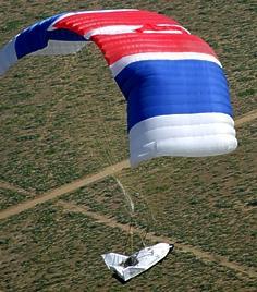 X-38 Paraglider Test Credit: NASA |
AKA: Spacewedge. Status: Cancelled 2000. Gross mass: 8,163 kg (17,996 lb). Height: 8.69 m (28.51 ft). Span: 4.42 m (14.50 ft).
Configuration based on earlier USAF X-24A but nose shows influence of Soviet Spiral design. The X-38 was designed for indefinite in-orbit storage, using cold nitrogen gas for attitude control. It reached the stage of paraglider drop tests before NASA funding dried up.
The X-38 rescue vehicle was also known as the X-35 (but that designation was already allocated by the USAF to another vehicle) and X-CRV (eXperimental - Crew Return Vehicle). The X-38 was sized for launch on the space shuttle, its wingspan fitting inside shuttle cargo bay. Its 1300 km cross-range allowed for landing opportunities ever two to three revolutions of the earth. As a rescue vehicle, it had consumables for only 9 hours of operation. Uniquely, it had no control stick, had completely automatic guidance, and could not be piloted to a landing at an airfield. Instead, after lifting reentry, drogue chutes deployed at Mach 0.8, followed by a steerable ram-air parafoil at Mach 0.25. Automated landing by parafoil was to be at a speed of 65 km/hr and a sink rate of 3.7 m/s.
When doubts about the availability of the Soyuz as an International Space Station lifeboat developed in 1995, NASA proceeded with in-house development of the X-38, a NASA Johnson concept. The spacecraft was a smaller version of the 1960's X-24 lifting body with a parafoil for landing. NASA hoped to break all precedents and develop this manned vehicle for under $ 500 million. Later the spaceframe could be stuffed with more elaborate life support, attitude control, and avionics systems to provide a manned spacecraft for launch from Ariane 5, Titan 4, Atlas 2, Delta 3, H-2, Proton, or Zenit (thereby finally achieving objective of canceled Hermes, X-24C, HOPE, and Uragan projects). In June 1996 NASA decided to use a modified Soyuz TM as the International Space Station in the short term, and the X-38 in the long term. However the X-38 was developed at a very slow pace, evidently kept alive as a contingency in case of collapse of Russian support of the ISS rather than a definite replacement.
Roll out of first of two slightly subscale 7.31 m long X-38 atmospheric test vehicles for use in parafoil landing tests was in November 1996. .After captive-carry flights from NB-52 beginning in July 1997, the two drop tests of vehicle in V-131 in 1998 indicated problems with the parafoil control system, which took some time to resolve. On 5 March 1999 the V-132 subscale version of the X-38 successfully deployed its parafoil, tested the rudders and flaps, and glided to a landing on the lakebed after a 9 minute flight. On 2 November 2000 the updated vehicle V-131R was drop-tested over Edwards AFB.
At that time the first space flight by X-38 vehicle V-201 was scheduled for 2002. However cutbacks in the ISS budget led to the X-38 being axed. This may also have been since it posed a low-cost alternate - and therefore a threat - to the much more elaborate shuttle-replacement systems that would evolve into the Orion CEV of 2005.
Detailed History and Development
From October 1991 to December 1996, NASA's Ames-Dryden Flight Research Facility (which became the Dryden Flight Research Center in 1984, Edwards, CA, conducted a research program known as the Spacecraft Autoland Project to determine the feasibility of the autonomous recovery of a spacecraft using a ram-air parafoil system for the final stages of flight, including a precision landing. The NASA Johnson Space Center (JSC) and the U.S. Army also participated in various phases of the program, with the Charles Stark Draper Laboratory developing the software for Wedge 3 under contract to the Army. Four generic spacecraft models (each called a Spacewedge or simply a Wedge) were built to test the feasibility of the concept and also of the use of a parafoil for delivering Army cargo. Technology developed during the program had also had application to the X-38 Crew Return Vehicle demonstrator. Spacewedge demonstrated precision flare and landing into the wind at a predetermined location. The program showed that a flexible, deployable system using autonomous navigation and landing was a viable and practical way to recover spacecraft.
NASA researchers conducted a flight test program in California to develop and refine the Spacewedge vehicle design. The first test vehicle (Wedge 1) was just 1.3 m long, and weighed 55 kg. It was initially launched from a hillside near Tehachapi to evaluate general flying qualities, including gentle turns and landing flare. Two of these slope soar flights were made on 23 April 1992 with approximately 30 kph winds, achieving altitudes of three to 15 m above the ground. The test program then moved to Rogers Dry Lake at Edwards AFB, and to a sport parachute (Skydive) drop zone at California City, CA.
A second vehicle (known as Inert Spacewedge or Wedge 2) was fabricated with the same external geometry and weight as Wedge 1. It was initially used to validate parachute deployment, harness design, and drop separation characteristics. Wedge 2 was inexpensive, without internal components, and considered expendable. It was first dropped from a Cessna U-206 Stationair on 10 June 1992 during Flight 3. A second drop of Wedge 2 verified repeatability of the parachute deployment system. The Wedge 2 vehicle was also used for the first drop from a Rans S-12 ultralight modified as a remotely piloted vehicle (RPV) during flight 9 on 14 August 1992. Wedge 2 was later instrumented and used for ground tests, mounted on top of a van, and became the primary test vehicle for the Phase II test series.
A total of 36 flight tests were made during Phase I, the last taking place on February 12, 1993. These flights verified the manual control and autonomous landing systems of the vehicle. Eleven of the tests were remotely controlled. Most were launched from the Cessna U-206 Stationair. Only flights 9 and 12 were launched from the Rans S-12 RPV.
Phase II of the program ran from March 1993 to March 1995, and encompassed 45 flights. It continued the research for NASA JSC, using a smaller, 77 A2 parafoil for higher wing (parachute) loading (0.10 kg/m2). For Phase II, NASA Dryden engineers developed a new guidance, control, and instrumentation system.
Phase III, encompassing 34 flights, evaluated the Precision Guided Airdrop Software (PGAS) system using Wedge 3 from 14 June 1995 to 20 November 1996. Researchers used Wedge 3 to develop a guidance system to be used by the Army for precision offset cargo delivery. The Wedge 3 vehicle was 1.3 m long, and was dropped at weights varying from 57 to 86 kg. Unlike Wedges 1 and 2, its flight objectives were not tied to the terminal recovery of a space vehicle, and it was not called a Spacewedge. (There was also a fourth wedge, but it never flew and served only as backup hardware to Wedge 3.)
The Spacewedge was a flattened biconic airframe joined to a ram-air parafoil with a custom harness. In the manual control mode, the vehicle was flown using radio uplink. In the autonomous mode, it was controlled using a small computer which received inputs from onboard sensors. Selected sensor data were recorded onto several onboard data loggers.
Two Spacewedge shapes, resembling half-cones with a flattened bottom, were used for four airframes that represented generic hypersonic vehicle configurations. Wedge 1 and Wedge 2 had sloping sides, and the underside of the nose sloped up slightly. Wedge 3 and Wedge 4 had flattened sides, to create a larger internal volume for instrumentation. The Spacewedge vehicles were 1.22 m long, 0.76 m wide, and 0.53 m high. The basic weight was 55 kg. Wedge 1 had a tubular steel structure, covered with plywood on the rear and underside to withstand hard landings. It had a fiberglass-covered wooden nose, and removable aluminum upper and side skins. Wedge 2, originally uninstrumented, was later configured with instrumentation. It had a fiberglass outer shell, with plywood internal bulkheads and bottom structure. Wedge 3 was constructed as a two-piece fiberglass shell, with a plywood and aluminum shelf for instrumentation.
A commercially-available 27 m2 ram-air parafoil was selected for Phase I tests. Such parachutes were commonly used by sport parachutists. The docile flight characteristics, low loading factor, and proven design allowed the project team to concentrate on developing the vehicle rather than the parachute. With the exception of lengthened control lines, the parachute was not modified. Its large size allowed the vehicle to land without flaring, and without sustaining damage. For Phase II and III, a smaller (7 m2) parafoil was used to allow for a wing (actually, parafoil) loading more representative of space vehicle or Army cargo applications.
The Spacewedge Phase I and II instrumentation system architecture was driven by cost, hardware availability, and program evolution. (During Phase I, Wedge 2 had an inert payload but was outfitted with instrumentation for Phase II.) The essential items consisted of the uplink receiver, Global Positioning System receiver and antenna, barometric altimeter, flight control computer, servoactuators, electronic compass, and ultrasonic altimeter. Added instrumentation included a video camera and camcorder, control position transducers, a data logger, and a pocket personal computer. NASA employees integrated these off-the-shelf components. Wedge 3 instrumentation was considerably more complex to accommodate the PGAS software system.
Spacewedge control systems had programming, manual, and autonomous flight modes. The programming mode was used to start up and configure the flight control computer. Researchers entered the landing coordinates, decision altitudes, and ground wind velocity at the landing site.
The manual mode used a radio control (RC) model receiver and uplink transmitter, configured to allow the ground pilot to enter either brake (pitch) or turn (yaw) commands. The vehicle reverted to manual mode whenever the transmitter controls were moved, even when the autonomous mode was selected.
The autonomous mode allowed the vehicle to navigate to the landing point, maintain the holding pattern while descending, enter the landing pattern, and initiate the flare maneuver. There were three decision altitudes: at the start of the landing pattern, at the turn to final approach, and upon flare initiation.
When at high altitude and offset from the landing point, the vehicle was commanded to fly to the landing point. If the landing point was reached while at or above the first decision altitude (typically set to 100 m), then the vehicle was commanded to fly a holding pattern until it descended below the decision altitude. The holding pattern was an upwind racetrack aligned with the wind (as input in the programming mode). Each lap of the racetrack pattern consumed approximately 150 m of altitude. Below the first decision altitude, the vehicle was commanded to enter the landing pattern.
The point to turn to final approach was based on a second decision altitude, typically 45 m to 60 m. This second altitude was a function of the wind and the position relative to the landing point. Once on final approach, the vehicle was commanded to maximum speed, steering commands were locked out, and the ultrasonic altitude sensor was activated.
At a final decision altitude of about 8 m, the flare was initiated by commanding full brake. Touchdown occurred approximately 4 seconds later.
Many Dryden employees and partners worked on this project. These included R. Dale Reed, who originated the concept of conducting a subscale flight test at Dryden. He also participated in the flight testing. Alexander Sim managed the project and participated in the flight tests and documentation. James Murray served as the principal Dryden investigator and as lead person for all systems integration for Phases I and II. He designed and fabricated much of the instrumentation for Phase II and was the lead person for flight data retrieval and analysis in Phases II and III. David Neufeld performed the wedge systems mechanical integration for all three phases and served as parachute rigger, among other duties. From Draper Lab, Philip Hattis served as the Project Technical Director for his organization's significant contributions to Phase III. For the Army, Richard Benney was the technical point of contact, while Rob Meyerson served as the technical point of contact for the NASA JSC and provided the specifications for the Spacewedges.
Potential NASA users for a deployable, precision, autonomous landing system include proposed vehicles with human crews as well as planetary probes and booster recovery systems. Military applications include the use of autonomous gliding parachute systems on aircraft ejection seats, and high-altitude, offset delivery of cargo to minimize danger to aircraft and crews. Such a cargo delivery system could also be used for providing humanitarian aid.
The Spacecraft Autoland Project, or Spacewedge, was an example of the innovative engineering work that was typical at NASA Dryden. Off-the-shelf equipment was used whenever possible in the project to keep costs low and to reduce development time. A relatively inexpensive Rans S-12 ultralight aircraft was modified as a RPV drop aircraft until the less labor-intensive unmodified Cessna U-206 had proved its viability. The four Spacewedge research vehicles were placed in storage at NASA Dryden Flight Research Center, Edwards, CA.
The Spacewedge technology was applied to the X-38 lifting body. The X-38 was expected to become the "lifeboat" for the International Space Station. The X-38 successfully demonstrated its precision landing capability using technology developed with the Spacewedge. On March 12, 1998, the X-38 made its first free flight. After dropping away from its B-52 mothership, the X-38 deployed a ram-air parafoil, and maneuvered to a precise landing on the Edwards Air Force Base bombing range.
Engineers at NASA's Dryden Flight Research Center, Edwards, Calif., and the Johnson Space Center, (JSC) Houston, Texas, were flight-testing the X-38, a prototype spacecraft that could become the first new human spacecraft built in the past two decades that travels to and from orbit. The vehicle was being developed at a fraction of the cost of past human space vehicles. The goal was to take advantage of available equipment, and already developed technology for as much as 80 percent of the spacecraft's design.
Using available technology and off-the-shelf equipment significantly reduces cost. The original estimates to build a capsule-type crew return vehicle (CRV) were more than $2 billion in total development cost. According to NASA project officials, the X-38 concept and four operational vehicles would be built for approximately one quarter of the original $2 billion cost.
Atmospheric drop tests of the X-38 at the Dryden Flight Research Center were to have continued for two years. Three test vehicles would be used. The drop tests would eventually increase in altitude to 15 km and would include longer flight times for the test craft before its parafoil was deployed.
Full-scale, unpiloted "captive carry" flight tests began at Dryden in July 1997 in which the vehicle remained attached to the NASA B-52 aircraft. Unpiloted free-flight drop tests from the B-52 began in March 1998. In 2000, an unpiloted space test vehicle was planned to be deployed from a Space Shuttle and descend to a landing on earth. The X-38 crew return vehicle was targeted to begin operations aboard the International Space Station (ISS) in 2003. In fact the program was canceled after the second drop test in 1999.
The immediate goal of the innovative X-38 project, was to develop the technology for a prototype emergency CRV, or lifeboat, for the ISS. The project also intended to at develop a crew return vehicle design that could be modified for other uses, such as a possible joint U.S. and international human spacecraft that could be launched on the French Ariane 5 booster.
In the early years of the International Space Station, a Russian Soyuz spacecraft would be attached to the station as a CRV. But, as the size of the crew aboard the station increased, a return vehicle that could accommodate up to six passengers would be needed. The X-38 design used a lifting body concept originally developed by the Air Force's X-24A project in the mid-1970's. After the deorbit engine module was jettisoned, the X-38 would glide from orbit unpowered like the Space Shuttle and then use a steerable, parafoil parachute, a technology recently developed by the Army, for its final descent to landing. Its landing gear would consist of skids rather than wheels.
Off-the-shelf technology didn't mean it was old technology. Many of the technologies used in the X-38 had never before been applied to a human spacecraft.
The X-38 flight computer was commercial equipment that was currently used in aircraft, and the flight software operating system was a commercial system already in use in many aerospace applications. The video equipment on the atmospheric vehicles was existing equipment, some of which had already flown on the Space Shuttle for other NASA experiments. The electromechanical actuators used on the X-38 came from a previous joint NASA, Air Force, and Navy research and development project.
An existing special coating developed by NASA would be used on the X-38 thermal tiles to make them more durable than the tiles used on the Space Shuttle. The X-38's primary navigational equipment, the Inertial Navigation System/Global Positioning System, was a unit already in use on Navy fighters.
Although the design could one day be modified for other uses such as a crew transport vehicle, the X-38 would strictly be used as a CRV in its original design. It was baselined with only enough life support supplies to last about nine hours flying free of the space station in orbit. The spacecraft's landing would be totally automated, although the crew would be able to switch to backup systems, control the orientation in orbit, pick a deorbit site, and steer the parafoil, if necessary. The X-38 CRV had a nitrogen cold gas attitude control system and used a bank of batteries for power. The spacecraft would be 8.69 m feet long, 4.42 m wide, and weigh about 7200 kg.
In-house development study of the X-38 concept began at JSC in early 1995. In the summer of 1995, early flight tests were conducted of the parafoil concept by dropping platforms with a parafoil from an aircraft at the Army's Yuma Proving Ground, Yuma, Arizona. In early 1996 a contract was awarded to Scaled Composites, Inc., of Mojave, Calif. to build three full-scale atmospheric test airframes. The first vehicle airframe was delivered to JSC in September 1996, where it was outfitted with avionics, computer systems, and other hardware in preparation for the flight tests at Dryden. A second vehicle was delivered to JSC in December 1996.
About 100 people worked on the project at Johnson, Dryden, and the Langley Research Center in Hampton, Va. This was the first time a prototype vehicle had been built-up in-house at JSC, rather than by a contractor; an approach that had many advantages. By building up the vehicles in-house, engineers had a better understanding of the problems contractors experienced when they built vehicles for NASA. JSC's X-38 team had a detailed set of requirements for the contractor to use to construct the CRVs for the ISS. This type of hands-on work was done by the National Advisory Committee on Aeronautics (NACA), NASA's predecessor, before the space age began. Dryden conducted model flights in 1995. The 1/6 scale-model of the CRV spacecraft using a parafoil parachute system was flown 13 times. The results showed that the vehicle had good flight control characteristics and also demonstrated good slideout characteristics.
Crew Size: 6. Orbital Storage: 4,000 days. RCS Coarse No x Thrust: Cold gas (nitrogen).
More at: X-38.
Family: Space station orbit, Spaceplane, US Rocketplanes. Country: USA. Launch Vehicles: Titan IIIB, Space Shuttle. Launch Sites: Edwards. Agency: NASA, OSC. Bibliography: 152, 158, 22, 4286, 48, 7036.
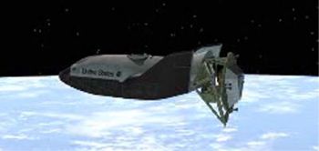
 | X-38 side shot Credit: NASA |
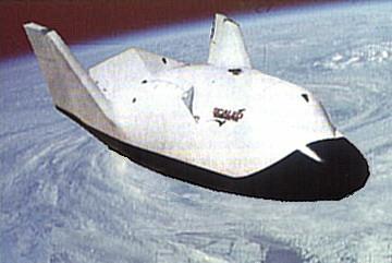
 | X-38 CRV X-38 Crew Rescue Vehicle. This vehicle is based on the old X-23/X-24A lifting body which was extensively tested in the 1960s. Credit: NASA via Marcus Lindroos |
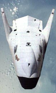 | X-38 overhead shot Credit: NASA |
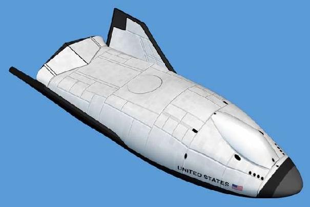
 | X-38 Credit: Manufacturer Image |
1991 December - .
- HL-20 Mock-up tests completed - .
Nation: USA.
Spacecraft: HL-20,
Space Station Freedom,
X-24A,
X-38.
NASA, North Carolina State University and North Carolina A&T University built a full-scale model of the HL-20 for human factors research on the concept. In the end, space station Freedom became the International Space Station. As the initial crew emergency rescue vehicle, the Russian Soyuz spacecraft was selected. However NASA, looking for a higher-capacity alternative and concerned about reliable availability of the Soyuz in the future, did begin development of the X-38 CERV in 1997. The X-38 was however based on the Johnson concept of parachute-assisted landing, and used the pure-USA X-24 lifting body shape....
1992 April 23 - .
- Spacewedge 1 first flight - .
Nation: USA.
Spacecraft Bus: Rescue.
Spacecraft: X-38.
NASA researchers conducted a flight test program to develop the Spacewedge vehicle design. The first test vehicle (Wedge 1) was just four ft long, and weighed 120 lb. It was initially launched from a hillside near Tehachapi; the test program then moved to Rogers Dry Lake at Edwards AFB, and to a sport parachute (Skydive) drop zone at California City, CA.
1992 June 10 - .
- Spacewedge 2 first flight - .
Nation: USA.
Spacecraft Bus: Rescue.
Spacecraft: X-38.
A second vehicle to test autonomous parasail spacecraft recovery was fabricated with the same external geometry and weight as Wedge 1. It was dropped from a Cessna U-206 and a Rans S-12 ultralight. A total of 36 flight tests were made, the last taking place on February 12, 1993. These flights verified the manual control and autonomous landing systems of the vehicle. Phase II of the program ran from March 1993 to March 1995, and encompassed 45 flights.
1995 During the Year - .
- X-38 development authorised. - . Nation: USA. Program: ISS. Spacecraft: ISS, X-38. When doubts about the availability of Soyuz developed in 1995, NASA proceeded with development of the X-38, a NASA Johnson concept - a smaller version of the X-24 lifting body with a parafoil..
1995 June 14 - .
- Spacewedge 3 first flight - .
Nation: USA.
Spacecraft Bus: Rescue.
Spacecraft: X-38.
Phase III, encompassing 34 flights, evaluated the Precision Guided Airdrop Software (PGAS) system using Wedge 3 from June 14, 1995 to November 20, 1996. Researchers used Wedge 3 to develop a guidance system to be used by the Army for precision offset cargo delivery. The Wedge 3 vehicle was 4 ft long, and was dropped at weights varying from 127 to 184 lb. Unlike Wedges 1 and 2, its flight objectives were not tied to the terminal recovery of a space vehicle, and it was not called a Spacewedge. (There was also a fourth wedge, but it never flew and served only as backup hardware to Wedge 3.)
1996 June - .
- Soyuz TMA, X-38 selected as ISS lifeboat over Alpha Lifeboat - . Nation: Russia. Program: ISS. Spacecraft: Alpha Lifeboat, ISS, Soyuz TMA, X-38. The Alpha lifeboat was based on the Zarya reentry vehicle with a solid retrofire motor and cold gas thruster package. The design was rejected in favor of use of modified Soyuz TM in short term, US X-38 in long term..
1996 November - .
- X-38 Rollout - . Nation: USA. Program: ISS. Spacecraft Bus: Rescue. Spacecraft: X-38. Roll out of first of two slightly subscale 7.31 m long atmospheric test vehicles for use in parafoil landing tests was in November 1996..
1998 March 12 - . Launch Site: Edwards. Launch Complex: Edwards.
- X-38 V-131 Flight 1 - . Nation: USA. Program: ISS. Spacecraft Bus: Rescue. Spacecraft: X-38. After dropping away from its B-52 mothership, the X-38 deployed a ram-air parafoil, and maneuvered to a precise landing on the Edwards Air Force Base bombing range..
1999 March 5 - . Launch Site: Edwards. Launch Complex: Edwards.
- X-38 V-132 Flight 1 - .
Nation: USA.
Program: ISS.
Class: Manned.
Type: Manned spaceplane. Spacecraft Bus: Rescue.
Spacecraft: X-38.
X-38 atmospheric test vehicle V-132 was dropped from carrier plane NB-52 # 8 at 16:17 GMT. The V-132 subscale version of the X-38 successfully deployed its parafoil and glided to a landing on the lakebed after a 9 minute flight. V-132 tested the rudders and flaps; the simpler V-131, which made two drop tests earlier, tested the parafoil control system.
2000 November 2 - . Launch Site: Edwards. Launch Complex: Edwards.
- X-38 V-131R drop-tested over Edwards AFB. - . Nation: USA. Program: ISS. Spacecraft Bus: Rescue. Spacecraft: X-38. The first space flight by X-38 vehicle V-201 was scheduled for 2002 at the time of this test; later ISS budget cutbacks would impact this plan..
Back to top of page
Home - Search - Browse - Alphabetic Index: 0- 1- 2- 3- 4- 5- 6- 7- 8- 9
A- B- C- D- E- F- G- H- I- J- K- L- M- N- O- P- Q- R- S- T- U- V- W- X- Y- Z
© 1997-2019 Mark Wade - Contact
© / Conditions for Use